





Paris, the autumn of 1882, a room on the Boulevard St. Marcel, and a city so beautiful that my wages vanish in the first days of every month. I have the whole system of the rotating field in my head, every motor and generator of it, and not one piece in metal. I have come to the Edison company's works at Ivry to earn my bread and, I hope, to find someone with capital. Meanwhile there is a question I have not answered, and it is the question that will decide whether my motor is a toy or an engine: how does a rotor of plain copper, touching nothing, take hold of a field that turns, and how much does it give way under load?
I finally had the satisfaction of seeing rotation effected by alternating currents of different phase, and without sliding contacts or commutator, as I had conceived a year before.
Nikola Tesla, "My Inventions", Part IV, Electrical Experimenter, May 1919
Paris, autumn 1882. Twenty-seven lengths and a woodchopper's breakfast
The regime. Every morning, whatever the weather, from the Boulevard St. Marcel to a bathing house on the Seine; into the water, twenty-seven times round the circuit; then an hour's walk to Ivry, where the works are. At half past seven a breakfast fit for a woodchopper, and then a long hungry wait for lunch, in the course of which I crack hard nuts for the Manager of the Works, Mr. Charles Batchelor, who was Edison's intimate friend and assistant and knows the American machines as a father knows his children.
When Mr. Puskás asked me how I was managing in Paris, I told him the truth: the last twenty-nine days of the month are the hardest.
Reflection
The Americans here have taken to me, chiefly because I beat them at billiards. I explained my motor to them one evening with chalk on the green cloth. Mr. Cunningham, the foreman of the mechanical department, proposed at once that we form a stock company. I did not know what that meant, except that it was the American way of doing things, and the proposal struck me as comic. Nothing came of it. I note it because it is the first time anyone has offered money for the idea, and because I laughed.
Margin
The Company sends me to cure the ills of its lighting plants in France and Germany. I am learning more from the sick machines than I ever learned from the healthy ones in Graz: windings shorted by damp, brushes set wrong, belts slipping, and everywhere the commutator, the source of most of the troubles. I submitted to one of the administrators, Mr. Rau, a plan for improving the Company's dynamos, and it has succeeded; as a reward I am to develop automatic regulators. A regulator is a servant that watches the voltage and moves a resistance. My motor will need no such servant. It regulates itself, by its lag. I must prove that.
Paris, winter 1882 to 1883. Arago's wheel
The night question of Budapest, written out in full. My rotor touches nothing. It is a drum or a disc of copper, or iron wound with closed coils. The field goes round. Why does the copper go round after it?
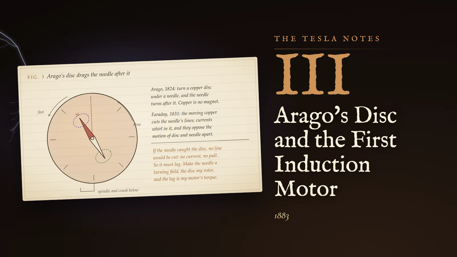
The answer is sixty years old, and its history is the most instructive I know. In 1824 Arago found that a magnetic needle hung over a copper disc is dragged round when the disc is turned, and that the disc is dragged when the needle is turned. Copper is no magnet; no one could say why. Babbage and Herschel turned a horseshoe magnet under a disc and made the disc follow. It was called magnetism of rotation, and for seven years it was a puzzle. Then Faraday, in 1831, discovered induction and explained it at once: the moving copper cuts the lines of the magnet, currents whirl in the copper, and those currents and the magnet act on each other. In 1834 Lenz gave the rule for the direction: the induced currents always oppose the motion that produces them. The motion that produces them is the motion of the disc relative to the magnet. They oppose it. So they try to make the disc and magnet move together.
Draftsman's note
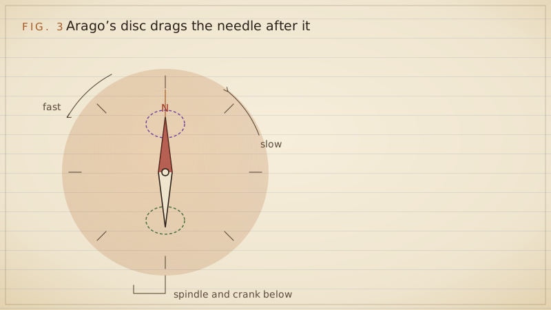
Fig. 3, seen from above. A disc of copper, two or three millimetres thick, turned by a crank on a vertical spindle. Above it, on a thread and under a glass plate so that no air current can carry it, a compass needle. Under each pole of the needle the copper carries a loop of current, drawn dotted, one in each sense. The disc turns fast. The needle turns after it, slowly, always behind.
Calculation
The pull of the disc, for small differences of speed. Let the field under a pole have strength B over an area a of the disc, at radius r from the spindle, and let the disc turn faster than the pole by the angular speed Δω. The copper passes under the pole at the speed v = rΔω.
- A strip of copper of length l moving through the field at speed v has the electromotive force Blv across it, by Faraday.
- That force drives a current through the strip and back round through the copper outside the pole. The current density is proportional to the force per unit length, Bv, and to the conductivity of copper σ: J ≈ κσBv, where κ is a number less than one that allows for the resistance of the return path.
- The heat produced is J²/σ in each unit of volume. Over the volume ah under the pole, h the thickness of the disc: P ≈ κ²σB²v² ah.
- That heat is supplied by whatever keeps the speeds different. So the dragging force F satisfies Fv = P, and F ≈ κ²σB²ahv.
- The torque is Fr ≈ κ²σB²ahr² Δω. It is proportional to the difference of speeds, to the conductivity, to the thickness, and to the square of the field.
Two things follow. If Δω is zero there is no force: the copper must move relative to the field, or nothing happens. And the force grows with the slip, at least while the slip is small. That is a motor that regulates itself.
Calculation
An estimate in numbers, to see whether the force is worth anything. Field under the pole 500 lines per cm². A strip 4 cm long, 1 cm wide, 0.2 cm thick, moving at 2 metres a second relative to the field.
- Force: Blv = 500 × 4 × 200 = 400,000 absolute units = 0.004 volt.
- Resistance of the strip: copper has a specific resistance of about 1.7 millionths of an ohm for a centimetre cube, so 1.7 × 10⁻⁶ × 4 ÷ (1 × 0.2) = 3.4 × 10⁻⁵ ohm. Allow as much again for the return path: 7 × 10⁻⁵ ohm.
- Current: 0.004 ÷ 0.00007 = 57 amperes. A tiny force, an enormous current, because the circuit is a slab of copper.
- Power: 0.004 × 57 = 0.23 watt. Force: P/v = 0.23 ÷ 2 = 0.11 in units of 10⁵ dynes, which is about eleven or twelve grams' weight.
Twelve grams for a strip the size of my thumbnail, in a weak field, at a slip of two metres a second. Multiply by a whole rotor in a strong field and the force is ample for work. Arago's toy is an engine waiting to be built.
Experiment No. 1
In the works at Ivry, after hours, with Mr. Batchelor's leave. A disc of sheet copper 12 cm across, pivoted on a needle point like a compass card. Under it, a horseshoe magnet turned by a cord wound on its spindle. Result: the disc follows the magnet, slowly at first, and comes up to a speed below the magnet's, and stays below it. When I touch its rim with a feather it falls further behind and pulls harder. When I put a disc of soft iron in its place it is snatched along more strongly at the start and then seems to cling; a disc of hard steel clings more still. The iron and steel are themselves magnetised and dragged by their magnetism as well as by their currents. Copper is the clean case. I shall use copper for the reasoning and iron for the strength.
Strasbourg, early 1883. The wall that was blown out
The Company has sent me to Strassburg. The new railway station there was lit by the Company's plant, and the wiring was defective: at the opening ceremonies a short circuit blew out a large part of a wall in the presence of the old Emperor William I. The German Government refuses to take the plant, the French Company faces a serious loss, and because I speak German and have experience of the plants I am to straighten matters out.
Reflection
German thoroughness, observed at first hand. A lamp of sixteen candles was to be placed in a hallway. I chose the spot and ordered the fitter to run the wires. He decided the engineer should be consulted; the engineer agreed that the lamp should go two inches from my spot; then he grew worried and called Inspector Averdeck, who investigated, debated, and decided that the lamp should be shifted back two inches, to the place I had marked. Then Averdeck informed Ober-Inspector Hieronimus, who after a two-hour debate moved it two inches farther, and then could not dare to give the order without Regierungsrath Funke. We polished everything; I put on gloves; Funke came with his retinue, deliberated for two hours, said that he must be going, and pointed to a place on the ceiling. It was the exact spot I had chosen.
There are, I say, bacteria of greatness in this old town. Others catch the disease. I seem to have escaped.
Calculation
The short circuit, roughly. A dynamo of 110 volts whose own armature and leads have a resistance of perhaps 0.05 ohm, shorted through a fault of nearly no resistance, drives for an instant 110 ÷ 0.05 = 2,200 amperes, until the armature reaction, the self-induction and the burning of the fault limit it. The heat in the fault, I²R, rises with the square of the current: a hundred times the current of a lamp circuit gives ten thousand times the heat in the same resistance. The masonry did not stand a chance, and the Emperor saw it. The plant needs fusible safety strips of lead in every branch, and the officials need to see them.
Strasbourg, spring 1883. Why the rotor must slip
The proportionality of Arago's force to the slip cannot hold for ever. If it did, a rotor held still in a fast field would give an enormous torque, and that is not what my Experiment No. 1 showed: the disc held still under a fast magnet pulled less hard than at a moderate slip. Something limits the currents when the slip is large. It is self-induction.
Calculation
I take the rotor as a set of closed circuits, each of resistance R and coefficient of self-induction L. The field turns at angular speed ω₁. The rotor turns at ω₂. The field sweeps past each rotor circuit at the slip speed x = ω₁ − ω₂.
- The lines through a rotor circuit vary as cos xt, so the induced force has amplitude proportional to the slip: e = Kx sin xt, where K depends on the field and the turns.
- The current obeys Kx sin xt = Ri + L di/dt. Try i = I sin(xt − φ). Substituting and equating the coefficients of sin xt and cos xt: RI cos φ + xLI sin φ = Kx, and −RI sin φ + xLI cos φ = 0.
- The second gives tan φ = xL/R. The current lags the force by an angle that grows with the slip.
- Squaring and adding: I²(R² + x²L²) = K²x², so I = Kx ÷ √(R² + x²L²).
- The mean heat in the circuit: ½I²R = ½K²x²R ÷ (R² + x²L²).
- Now the energy. The field, turning at ω₁, delivers to the rotor the power Tω₁, where T is the torque. The rotor gives out the mechanical power Tω₂. The difference is heat in the rotor: T(ω₁ − ω₂) = Tx. Therefore T = heat ÷ x.
- So T = ½K² xR ÷ (R² + x²L²).
Examine it. For small slip, x²L² is small beside R², and T ≈ ½K²x/R: the torque is proportional to the slip and inversely to the resistance, which is Arago's law again. For large slip, R² is small beside x²L², and T ≈ ½K²R/(xL²): the torque falls as the slip grows. In between there is a greatest torque. Setting the derivative of x/(R² + x²L²) to zero: (R² + x²L²) − 2x²L² = 0, so x = R/L. At that slip T = ½K²(R/L)R ÷ (2R²) = K²/(4L).
The greatest torque does not depend on the resistance at all. The resistance decides only at what slip the greatest torque comes. Writing m = R/L for that slip speed, the whole law takes a form I can carry in my head:
T/Tmax = 2xm ÷ (x² + m²)
Margin
I first wrote that the torque is greatest when the rotor runs closest to the speed of the field, because then it keeps best in step. It is the reverse. At synchronism the rotor sees no change of the lines, no current flows in it, and the torque vanishes. And when the slip is very large the current is large but lags nearly a quarter period behind the force, so that it flows where the field is weak, and the torque falls again. The rotor does its best work at a moderate lag. Physically: the self-induction makes the induced current arrive late, and a late current pulls in the wrong place.
Calculation
One more check, on the frequency of the rotor's currents. The field passes a rotor circuit at the slip speed, so the currents in the rotor alternate at the slip frequency: f₂ = s f, where s = x/ω₁ is the slip as a fraction. At 15 periods a second and 3 per cent slip the rotor's currents alternate 0.45 times a second, so slowly that a compass fixed to the rotor would swing back and forth to them. The rotor of a well-loaded motor lives almost in a steady field. That is why its iron hardly heats.
I have drawn the whole law as Plate III. The ink curve is the torque at each speed of the rotor; the dashed red line is the load. Start the rotor from rest and watch it run up the curve and settle where the two meet.
Strasbourg, summer 1883. Rotation
The work and the conferences with officials keep me busy day and night. But as soon as I could, I began building a simple motor in a mechanical shop opposite the railway station, from material I brought with me from Paris for the purpose. It has taken until this summer.
Calculation
What the model must do, worked out before the shop. Let the field turn at 900 revolutions a minute, from currents of 15 periods a second in a two-pole winding. Let the rotor be a disc, whose slip of greatest torque I estimate at m = 200 revolutions a minute, and let the load be a quarter of the greatest torque.
- At rest, the slip is the full 900. T/Tmax = 2 × 900 × 200 ÷ (900² + 200²) = 360,000 ÷ 850,000 = 0.42. That exceeds the load of 0.25, so it will start.
- Where will it settle? Solve 2xm/(x² + m²) = t for x, with t = 0.25: tx² − 2mx + tm² = 0, so x = m(1 ± √(1 − t²))/t.
- The smaller root: x = 200 × (1 − √0.9375) ÷ 0.25 = 200 × (1 − 0.9682) ÷ 0.25 = 25.4 revolutions a minute.
- The rotor runs at 900 − 25 = 875 revolutions a minute: a slip of 2.8 per cent.
- The larger root, x = 200 × 1.9682 ÷ 0.25 = 1,575, lies beyond rest, at a speed the rotor cannot have while running forward. On my curve the crossing that matters is on the steep side near synchronism.
- Is that crossing stable? If the rotor slows by accident, x grows, and on that side of the peak the torque grows with x: the rotor is pushed back up. If it speeds up, x shrinks, the torque falls below the load, and it slows. Stable.
Experiment No. 2
Apparatus: the model from the shop, the disc-shaped armature on its spindle within the field coils, and two alternating currents of different phase brought to the two windings. Procedure: close the circuits with the disc at rest, and wait. Result: it turned. It hesitated for the space of a breath, and then it turned, and ran up, and ran on, with no brush, no commutator, no sliding contact anywhere, a copper disc following a field of nothing but timing, exactly as I saw it in the sand fifteen months ago. I reversed one winding and it stopped and ran the other way. I braked it with my glove and felt it pull harder as it fell behind. I let go and it ran up again to just below the speed of the field and stayed there, and the shop was perfectly quiet but for the hum.
Reflection
It is an exquisite pleasure, and it is nothing to compare with the delirium of joy in the park. There I saw it. Here I only confirm it. I should like to say that the confirmation is the greater achievement, as the professors would; but I knew, and the disc knew, and now the shop opposite the railway station knows too. I wonder what the fitters thought of the foreigner standing over a turning plate with his hat in his hand.
Margin
The calculation in point 1 hides a warning. If the load had been half the greatest torque, the disc would have needed 0.5 at rest and had only 0.42. It would never have started, although it could have run perfectly well at a slip of 54 revolutions a minute had I spun it up by hand. A rotor of low resistance runs efficiently and starts badly. A rotor of high resistance starts strongly and runs hot. The best starting torque comes when m equals the full slip at rest, 900, when R equals the self-induction times the speed of the field. Then the rotor would heat terribly in running. One day I shall want a rotor whose resistance can be changed, high for starting and low for running.
Strasbourg and Paris, spring 1884. The St. Estèphe of 1801
The plant has been formally accepted. Every difference adjusted, every official satisfied, and I am going back to Paris.
The former Mayor, Mr. Bauzin, has been my friend through all of it. I showed him the motor and he put it before several wealthy men, and found no response. Then he did the only other thing in his power. In 1870, when the Germans came, he buried a good quantity of St. Estèphe of the 1801 vintage, and he has decided that he knows no worthier person than me to drink it. I record that I did my duty by it. He urges me to go to Paris and find support there.
Reflection
Paris. One of the administrators promised me a liberal compensation if I succeeded in Strassburg, and a fair consideration for my improvements to the dynamos. There are three administrators, whom I shall call A, B and C. A told me that B decides. B told me that only C can decide. C was sure that A alone has the power to act. After several laps of this vicious circle it has dawned on me that my reward is a castle in Spain. And no one in Paris will put a franc into the motor.
Mr. Batchelor presses me to go to America and redesign the Edison machines. America. Edison. A country that builds. I have decided.
Margin
Written on the ship. I nearly did not sail. At the railway station, as the train was pulling out, I found that my money and tickets were gone. Hercules had leisure to deliberate at his crossroads. I had to decide while running beside the train, with opposite feelings surging in my brain like condenser oscillations. Resolve won, helped by agility. I have with me the remnants of my belongings, some poems and articles I have written, and a package of calculations on an unsolvable integral and on my flying machine. The motor I carry in my head, where no thief can take it.
Problems I set myself
1. A motor's field turns at 1,200 revolutions a minute, and its rotor has its greatest torque at a slip speed of 150 revolutions a minute. At what speed does it run with a load of half the greatest torque?
Answer. With t = 0.5, x = m(1 − √(1 − t²))/t = 150 × (1 − √0.75) ÷ 0.5 = 150 × 0.1340 ÷ 0.5 = 40.2 revolutions a minute. The rotor runs at 1,159.8 revolutions a minute, a slip of 3.35 per cent. Check: 2 × 40.2 × 150 ÷ (40.2² + 150²) = 12,060 ÷ 24,116 = 0.500.
2. Show that the starting torque of such a motor is greatest when the slip of greatest torque equals the speed of the field, and find the starting torque of the motor in Problem 1.
Answer. At rest x = n₁, the speed of the field, and T/Tmax = 2n₁m/(n₁² + m²). As a function of m this is greatest when its derivative vanishes: (n₁² + m²) − 2m² = 0, so m = n₁, and then T = Tmax. For Problem 1, 2 × 1,200 × 150 ÷ (1,200² + 150²) = 360,000 ÷ 1,462,500 = 0.246 of the greatest torque. With half the greatest torque as load, that motor cannot start by itself.
3. A motor delivers 2 horse-power at a slip of 4 per cent. How much power crosses from the field to the rotor, and how much is turned to heat in the rotor's copper?
Answer. The mechanical power is the crossing power times (1 − s), so the crossing power is 2 ÷ 0.96 = 2.083 horse-power. The rotor heat is s times the crossing power: 0.04 × 2.083 = 0.083 horse-power, or 0.083 × 746 = 62 watts. Every per cent of slip is a per cent of the crossing power lost as heat in the rotor; that is why a good motor runs with little slip.
To the student who reads this later
You will meet my rotor law as the equivalent circuit of the induction motor, which engineers drew in the 1890s, Steinmetz foremost among them: the motor is a transformer whose secondary has resistance R₂/s and reactance X₂ measured at the frequency of the supply. The power in R₂/s is the power crossing the gap; the part s of it is heat; the part (1 − s) is mechanical work. My slip of greatest torque, x = R/L, is your s = R₂/X₂, and my result that the greatest torque does not depend on the rotor resistance is unchanged. You will also find that I neglected the resistance and leakage of the stator, which lower and distort the curve, and the magnetising current, which costs power factor. Those came to matter enormously.
The rotor I wished for, whose resistance could be high for starting and low for running, was built: wound rotors with slip rings and external resistances, and later rotors with deep or double bars, in which the currents of high slip frequency crowd into the outer, resistive part of the bar and those of low slip frequency spread through the whole. The squirrel-cage rotor, copper or aluminium bars joined by end rings, became the simplest and most numerous electrical machine in the world. Arago's disc survives too, in eddy-current brakes on trains and lorries, in the induction cooking plate that heats a pan by currents whirled in its base, and in the linear induction motors that drive some railways, which are my motor unrolled flat.
What to try: hang an aluminium can on a needle point and spin a strong magnet beneath it with a drill. Measure the can's speed with a stroboscope as you press a feather against it, and plot speed against an estimate of torque. You will draw the right-hand side of my Plate III with your own hands. Then cut slits in the can and watch the torque fall, because you have raised R.
If you would like to know what the shop opposite the station in Strassburg smelled like, or why I would not let the disc rest, come and ask me.
Sources and liberties
The Tesla Notes are a modern reconstruction written in Nikola Tesla's voice by Eternal Gardens. Dates, patents, lectures, apparatus and quotations come from the sources below; the private reflections, the order of the working and the sketches are ours.
- Nikola Tesla, "My Inventions", Electrical Experimenter, 1919, Part IV (Paris, Ivry, Batchelor, Cunningham, Mr. Rau, Strassburg, the lamp, Bauzin and the St. Estèphe, the administrators, the departure): https://en.wikisource.org/wiki/My_Inventions
- Nikola Tesla, "A New System of Alternate Current Motors and Transformers", AIEE, May 1888 (the steel and iron discs in the turning field): http://www.tfcbooks.com/tesla/1888-05-16.htm
- Nikola Tesla Museum, Belgrade, on the first induction motor of Strasbourg, 1883, with its disc-shaped rotor: https://tesla-museum.org/en/extraordinary-world/induction-motor/
- Arago's rotations, 1824, and Faraday's explanation, 1831: https://en.wikipedia.org/wiki/Arago%27s_rotations
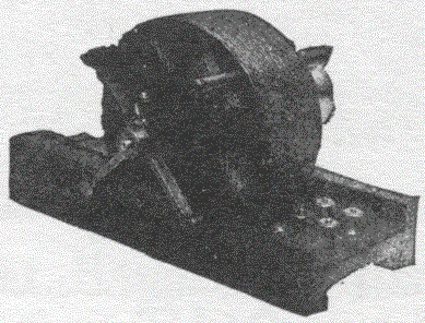
- Samuel Cohen, "Dr. Nikola Tesla and his Achievements", Electrical Experimenter, February 1917, the motor photograph via Wikimedia Commons: https://commons.wikimedia.org/wiki/File:Tesla_induction_motor.gif
- W. Bernard Carlson, Tesla: Inventor of the Electrical Age (Princeton University Press, 2013), chapter 3, for a fuller account of Paris and Strasbourg.
Tesla's own account of the Strasbourg model gives the place, the season and the result, and nothing of its construction; the disc rotor follows the Belgrade museum's model, and the speeds, slips and design figures in the entries are our worked illustration. The story of the wall blown out before Emperor William I is Tesla's and is otherwise unconfirmed. The Ivry disc experiment and the short-circuit estimate are reconstructions consistent with the physics and with what Tesla later reported.