





Colorado Springs, the 18th of May 1899. The train left me on a plateau two thousand metres above the sea, with the mountains standing up in the west like a wall and the plains running east to the edge of sight. I have come here with Colonel Astor's money, my friend Curtis's promises of land and current, crates of glass jars, coils of copper and a question that has followed me out of New York: how great an electrical vibration can one man build, and how will he know its pitch before he hears it? In the Houston Street laboratory the ceiling stopped me. Here the only ceiling is the sky, and the sky is full of lightning.
"First, to develop a transmitter of great power; second, to perfect means for individualizing and isolating the energy transmitted; and, third, to ascertain the laws of propagation of currents through the earth and the atmosphere."
Nikola Tesla, "The Transmission of Electric Energy Without Wires", Electrical World and Engineer, 5 March 1904
Colorado Springs, 18 May 1899. The plateau and the barn
Curtis has found me a site on the highest local ground, called Knob Hill, on the open prairie east of the town, between the School for the Deaf and Blind and the Union Printers Home. The station will be a plain wooden barn, built quickly and without ornament. I have asked for two things the carpenters think eccentric: a roof that can be rolled back, so that a mast may rise through it and the discharges may have the open air, and a floor large enough to hold a coil of some fifteen metres in diameter. The power company will bring alternating current from its line. I have arranged to pay nothing for it in the beginning, which is a sentence I hope I shall not regret.
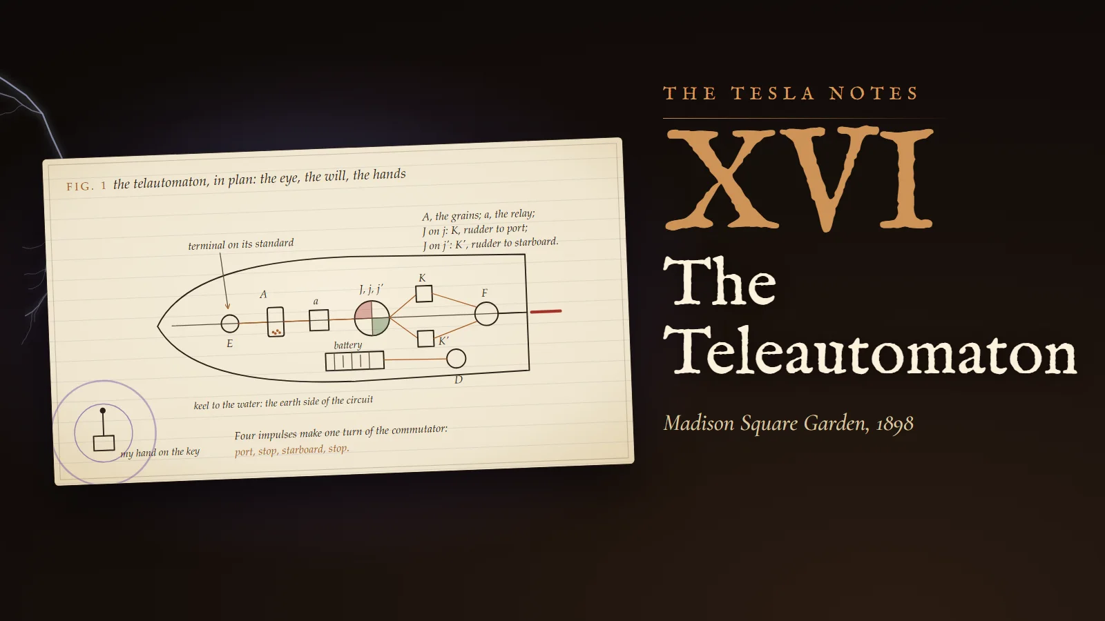
I set down here, so that I do not forget them, the three things I came to do. I must build a transmitter of great power. I must learn to individualise its energy, so that a receiver answers to it alone. And I must learn how currents travel through the earth and the air. The first is a question of copper, glass and nerve. The second I have half answered in New York with my teleautomaton and its tuned circuits. The third is the reason for coming to a country where nature makes my experiments for me every afternoon.
Calculation
What the thin air gives me and takes from me.
- The barometer stands near 24 inches of mercury here, against about 30 at the sea.
- At the same temperature the density of the air is in proportion to the pressure: 24 ÷ 30 = 0.80.
- Over long gaps the striking distance of a spark at a given pressure of electricity grows, very roughly, as the density falls. A coil that throws a spark of ten feet in New York may throw something like 10 ÷ 0.80 = 12.5 feet here.
- The same law works against me at the terminal: the charge leaks from a sphere into thin air at a lower surface force, about four fifths of what it would bear at the sea.
So I shall see longer sparks than I deserve and hold less tension than I want. I must keep both facts in mind when I read my own measurements, or I shall flatter myself.
Reflection
Tonight I walked to the edge of the field. A storm stood over the mountains, forty or fifty kilometres off, and the flashes came so often that the peaks seemed to be lit from inside. I counted between flash and thunder and gave it up: the thunder of one flash was overtaken by the light of the next. In New York I spent nights coaxing a spark of sixteen feet out of my coils, and here the sky throws discharges miles long without effort. I do not feel small. I feel that I have arrived at the right school.
Colorado Springs, 15 to 22 June 1899. The first sparks, and an order for a mile of wire
The building is up and the first oscillator runs. I record its state exactly, because everything that follows will be a correction of it.
Experiment No. 1
Apparatus, 15 June. Supply transformer worked at 200 volts on its low side. The break interrupts the primary circuit from 800 to 1,200 times a second. The primary is a single turn made of 37 wires of No. 9 gauge laid together into a cable. The secondary has 14 turns, averaging 130 feet each, which is 14 × 130 = 1,820 feet of wire. For the ground I have driven a gas pipe about twelve feet into the earth.
Result: a spark about five inches long, but very thick and noisy. It is a poor spark for so much copper. The fault, I think, lies first in the ground. On the 16th I sank a plate of 20 by 20 inches at a depth of twelve feet, poured water round it, and brought the resistance of the earth connection down to 14 ohms. A transmitter that means to work upon the earth must first hold the earth firmly.
Margin
On the 18th I measured self-inductances by the Maxwell method, with a wire bridge and a telephone, against a standard condenser of half a microfarad. The telephone is the most faithful instrument in the station: when the bridge is balanced it falls silent, and silence is easier to judge than any needle. On the 22nd I noted a curious rule which I do not yet understand. The sparks are strongest when the capacity of the primary is a whole multiple of a certain value, a·C₁ with a a whole number, especially 2 or 4. Resonance is announcing itself before I have prepared a seat for it.
Calculation
I have ordered about 11,000 feet of No. 10 wire, Brown and Sharpe gauge, for a secondary of 80 turns averaging 131 feet. Before the bill comes I check the weight.
- Length wanted: 80 × 131 = 10,480 feet, so 11,000 feet allows for leads and waste.
- Diameter of No. 10: 0.1019 inch. Section: π × 0.1019² ÷ 4 = 0.008155 square inch.
- Copper weighs 0.321 pound to the cubic inch. One foot (12 inches) of the wire: 0.008155 × 12 × 0.321 = 0.03141 pound.
- For 11,000 feet: 11,000 × 0.03141 ≈ 345.5 pounds.
The invoice says 345.4 pounds. The difference is the tenth of a pound I will lose on the floor.
Colorado Springs, 29 June to 3 July 1899. The extra coil, and the length of a wave
On the 29th I made the first good trial of a secondary of 36 turns of No. 10 cord, spaced about one and seven eighths inches, with a self-induction of about 5 × 10⁷ centimetres. To it I joined an additional coil: 240 turns on a drum six feet long and two feet across, of about 10⁷ centimetres. This additional coil has no partner. It is connected to the secondary at one end only, and its other end is free. The secondary drives it; nothing drives it back.
The next day I wrote the comparison that I believe is the key. The additional coil acts like the momentum of a pendulum. The secondary gives it a push at the right moment of each swing, and the coil, free at its top, swings higher and higher until its losses equal what it receives. I shall call it from now on the extra coil.
On 2 July I set down the principle on which every later element must rest. In my own words of that day: "First assumption on which to base calculations of other elements is made by deciding on the wave length of the disturbances." The wire of the secondary is to be one quarter of that wave. The capacity at the free terminal is to balance the self-induction. The primary condenser must be large enough to swallow the whole output of the transformer. I will choose the wave first and let the copper follow.
Calculation
3 July. Good resonance with 15 jars on each side of the primary. The two banks stand in series, so the capacity is that of seven and a half jars.
- Capacity of the primary: C = 7.5 × 0.003 = 0.0225 microfarad = 2.25 × 10⁻⁸ farad.
- Self-induction of the primary, six turns in series: L ≈ 36 × 7 × 10⁴ = 2.52 × 10⁶ centimetres = 2.52 × 10⁻³ henry.
- Kelvin's period: T = 2π√(LC) = 2π√(2.52 × 10⁻³ × 2.25 × 10⁻⁸) = 2π√(5.67 × 10⁻¹¹).
- √(5.67 × 10⁻¹¹) = 7.53 × 10⁻⁶; so T = 4.73 × 10⁻⁵ second and n = 1/T ≈ 21,100 per second.
- In the notebook that day I wrote n ≈ 20,700, my inductance being taken a little larger. Either figure serves.
- Wave length: λ = 186,000 miles per second ÷ 20,700 ≈ 9 miles, and the quarter wave ≈ 2.25 miles.
The secondary is one mile of wire. If the wire were the whole story, it would answer to a wave of four miles, not nine. Yet it resonates at the slower rate. I wrote the reason at once: the secondary is not a bare wire, it is a wire with capacity distributed along its whole length, turn beside turn, and every bit of that capacity must be filled and emptied in each period. Capacity slows the vibration. The coil is electrically longer than its copper.
The second arrangement of the day: the 40 turns of the secondary, one mile of No. 10, together with a coil of 260 turns on the drum of 2 by 6 feet. Capacity of the coil about 1,532 centimetres, of the secondary about 1,080; together about 2,612 centimetres. Total self-induction about 62 × 10⁶ centimetres. Then, in my own units, with c = 3 × 10¹⁰ centimetres per second:
T = 2π√(LC)/c = 2π√(62 × 10⁶ × 2,612)/(3 × 10¹⁰) = 2π × 402,400/(3 × 10¹⁰) ≈ 8.43 × 10⁻⁵ second, n ≈ 11,900.
I had written 11,800. The extra coil has halved the pitch of the system. A free coil on top of a driven one is a lever on frequency.
Draftsman's note
The secondary frame, as measured on the 4th: 36½ turns on a tapering frame, base about 51 feet, the sides inclined at 45°, like a low fence leaning inward round the room. Six coils of No. 10 wire, together 5,315 feet, which is a mile within a few yards (1,610 metres). Resistance 5.55 ohms. Self-induction with 40 turns about 42 × 10⁶ centimetres. The primary turns lie outside the secondary at floor level. The extra coil stands in the middle of the room on its own insulated base, its lower end joined to the top of the secondary, its upper end carried to a ball. Draw the room as a man would see it from the door: a fence, a column, a sphere.
Reflection
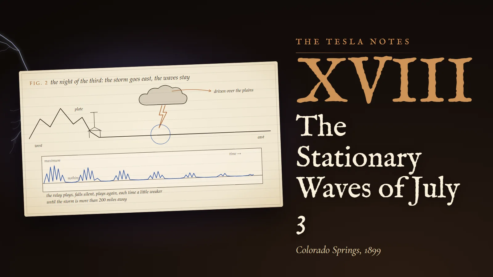
Late that night, the 3rd of July, a storm broke over the mountains and went away east over the plains, and my instruments told me something I cannot yet write calmly. It belongs to another page of this notebook. I mention it here only because I worked the figures above in the afternoon without the least idea that the evening would change what the figures were for.
Colorado Springs, 6 to 21 September 1899. A quarter wave wound on a drum
I write it as I wrote it on the 6th: "The tension on extra coil terminal (a ball of 38 cm. capacity) was over 3 million volts." It is an estimate, made from the spark lengths and the dimensions of the terminal, and I trust it to perhaps a quarter. But it is three times what I have ever had before, and the ball streams continuously, as if the air could not keep its hands off it.
On the 7th I wound a new coil to understand the extra coil by itself: 400 turns of wire on a drum of 10 inches, with a self-induction of about 2,000,000 centimetres. I mean to treat it as a quarter wave of wire.
Calculation
- Length of the wire: 400 turns × π × 10 inches = 12,566 inches ≈ 1,047 feet. Allowing for the thickness of the wire on the drum I take the effective quarter wave as 1,010 feet.
- Wave length: λ = 4 × 1,010 = 4,040 feet.
- Velocity of light in feet: 186,000 × 5,280 = 982,080,000 feet per second.
- Frequency: n = 982,080,000 ÷ 4,040 ≈ 243,000 per second. I entered 245,500, and the difference is within what I know of the length.
Now the same coil by Kelvin's formula, to find what capacity the coil itself must have for the two pictures to agree. With n = 245,500 and L = 2 × 10⁶ centimetres, in my units:
- T = 1/n = 4.073 × 10⁻⁶ second.
- T = 2π√(LC)/c, so √(LC) = cT/(2π) = 3 × 10¹⁰ × 4.073 × 10⁻⁶ ÷ 6.283 = 19,450 centimetres.
- LC = 3.783 × 10⁸, and C = 3.783 × 10⁸ ÷ 2 × 10⁶ ≈ 189 centimetres.
The coil behaves as if a condenser of 189 centimetres were hung on its free end. That capacity is spread through every turn. And now the important step. A sphere has a capacity in centimetres exactly equal to its radius in centimetres, when it stands alone far from other bodies. The ball of the 6th was 30 inches across, its radius 15 inches, which is 15 × 2.54 = 38.1 centimetres. Its capacity is therefore 38.1 centimetres, the very figure I wrote. Put the ball on top of the drum coil:
n′ = n √(189/(189 + 38.1)) = 245,500 × √0.8323 = 245,500 × 0.9123 ≈ 224,000 per second.
The ball lowers the pitch by about nine parts in a hundred. A larger ball would lower it further. The free end is the place where a little capacity buys a great deal of slowness, because the voltage is greatest there and every centimetre of capacity at the top must be charged to the full height of the swing.
I have drawn the coil as Plate XVII. The coil stands at the left, the ball above it. Beside it are the two curves that live along the wire: the current, greatest at the grounded base and falling to its least at the top; and the voltage, nothing at the base and greatest at the top. They are a quarter of a period apart in time. Move the ball and watch the resonance move; then press "Find resonance" and see the sweep I make by hand with the regulating coil.
Margin
The plate treats the coil as a line of distributed capacity and gives about 227,000 for the 38 centimetre ball, where my lumped figure gave 224,000. The two methods differ by a little over one part in a hundred, which is less than my uncertainty in the length of the wire. I note the agreement and move on. On the 21st, planning the mast, I wrote: "The electrostatic capacity will reduce turns on coil to probably less than one half." The large terminal and the extra coil are one instrument. What capacity I add above, I may take away in copper below.
Experiment No. 2
19 September. I tried the extra coil and the secondary in several proportions: each a quarter wave; the extra coil a half wave on a quarter wave secondary; the extra coil three quarters on a quarter. The best effects come when the whole system, from the ground plate through the secondary and the extra coil to the free terminal, adds to one quarter wave or to an odd number of quarters. A half wave extra coil puts a node of voltage at its top, which is exactly where I want the greatest swing. That arrangement I struck out.
Colorado Springs, 6 to 23 October 1899. Three ways to a capacity
October is the month of measurement. I have spent more hours finding the capacity of the vertical conductor than on any other single question, and I am not ashamed of it. A transmitter whose constants are guessed is a bell rung blindfold.
Calculation
6 October, the electrodynamometer method. I passed the low-frequency current of the supply through the secondary of 16 turns and read the pressure and the current.
- Angular frequency of the supply: p = 880 per second (about 140 cycles).
- Pressure E = 122.5 volts; current I = 13.8 amperes; resistance R = 2.804 ohms, measured separately.
- Impedance: Z = E/I = 122.5 ÷ 13.8 = 8.877 ohms.
- The impedance is the hypotenuse of a right triangle whose sides are R and pL: pL = √(Z² − R²) = √(78.80 − 7.86) = √70.94 = 8.423 ohms.
- L = 8.423 ÷ 880 = 0.00957 henry, or 9,570,000 centimetres.
On the 17th, with the connections altered, the same method gave L = 8.41/880 = 0.0095568 henry. The two agree to one part in seven hundred. I believe them.
The three ways I now use for capacity, written down so that whoever reads this may repeat them:
- The bridge. As in June: a Maxwell bridge with a telephone, balancing the unknown against the half microfarad standard. Good for condensers, poor for a mast in the open air.
- The deflection. Charge the unknown and the standard to the same pressure and discharge each through the galvanometer; the throws stand in the ratio of the capacities. On 24 July I found the secondary to be 3,600 centimetres this way, and I judged it right within half of one per cent.
- The resonance. Tune the system exactly; add the unknown (a sphere, a wire, a raised ball); then change the regulating coil until resonance returns. From the change of period the capacity follows.
The resonance method in numbers, with the drum coil of September as a model. Suppose the coil alone rings at n₁ = 245,500 and with the ball at n₂ = 224,000. Since n is in inverse proportion to √C:
C₀ + ΔC = C₀ (n₁/n₂)², so ΔC = C₀[(n₁/n₂)² − 1] = 189 × [(1.0960)² − 1] = 189 × 0.2012 ≈ 38.0 centimetres.
The ball is found again, from its effect alone. That is the beauty of the method: I never touch the thing I measure.
Experiment No. 3
23 October. An 18 inch ball on a light wooden structure 60 feet high, raised by stages from 9 feet 5 inches to 58 feet 9 inches above the ground, its capacity taken by resonance at each stage. My entry that night: "the augmentation of the capacity as the ball was elevated was in a simple proportion to the height."
Margin
This result does not mean what it appears to mean, and I must be careful. A ball near the ground has its capacity increased by its image in the earth. By Lord Kelvin's method of images, a sphere of radius r whose centre stands at height h has, to a first approximation, C ≈ r(1 + r/2h).
- The 18 inch ball: r = 9 inches = 22.86 centimetres.
- At 9 feet 5 inches, h = 287 centimetres: C ≈ 22.86 × (1 + 22.86/574) = 22.86 × 1.040 = 23.77 centimetres.
- At 58 feet 9 inches, h = 1,791 centimetres: C ≈ 22.86 × (1 + 22.86/3,582) = 22.86 × 1.006 = 23.01 centimetres.
The ball by itself loses three quarters of a centimetre as it rises. What grows in simple proportion to the height must therefore be the wire that carries it up, a long thin conductor whose capacity increases with its length. The vertical wire is half my terminal. I had been measuring the lead and crediting the ball.
Colorado Springs, 7 to 17 October 1899. The mast, the streamers and the size of things
On the 17th I recorded the vertical structure, built chiefly for the investigation of earth vibrations. I give the figures as they stand in the entry.
Draftsman's note
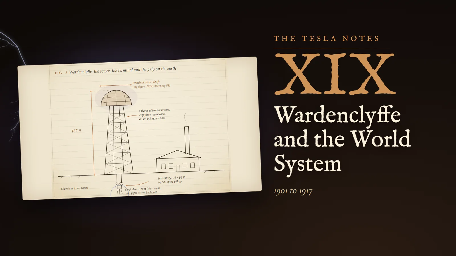
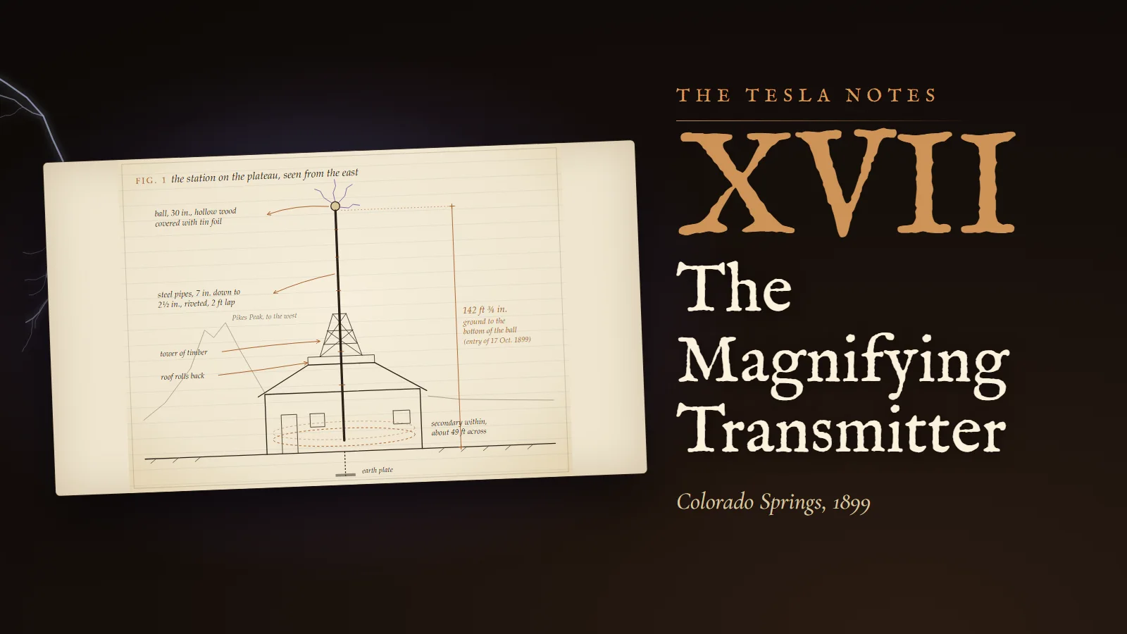
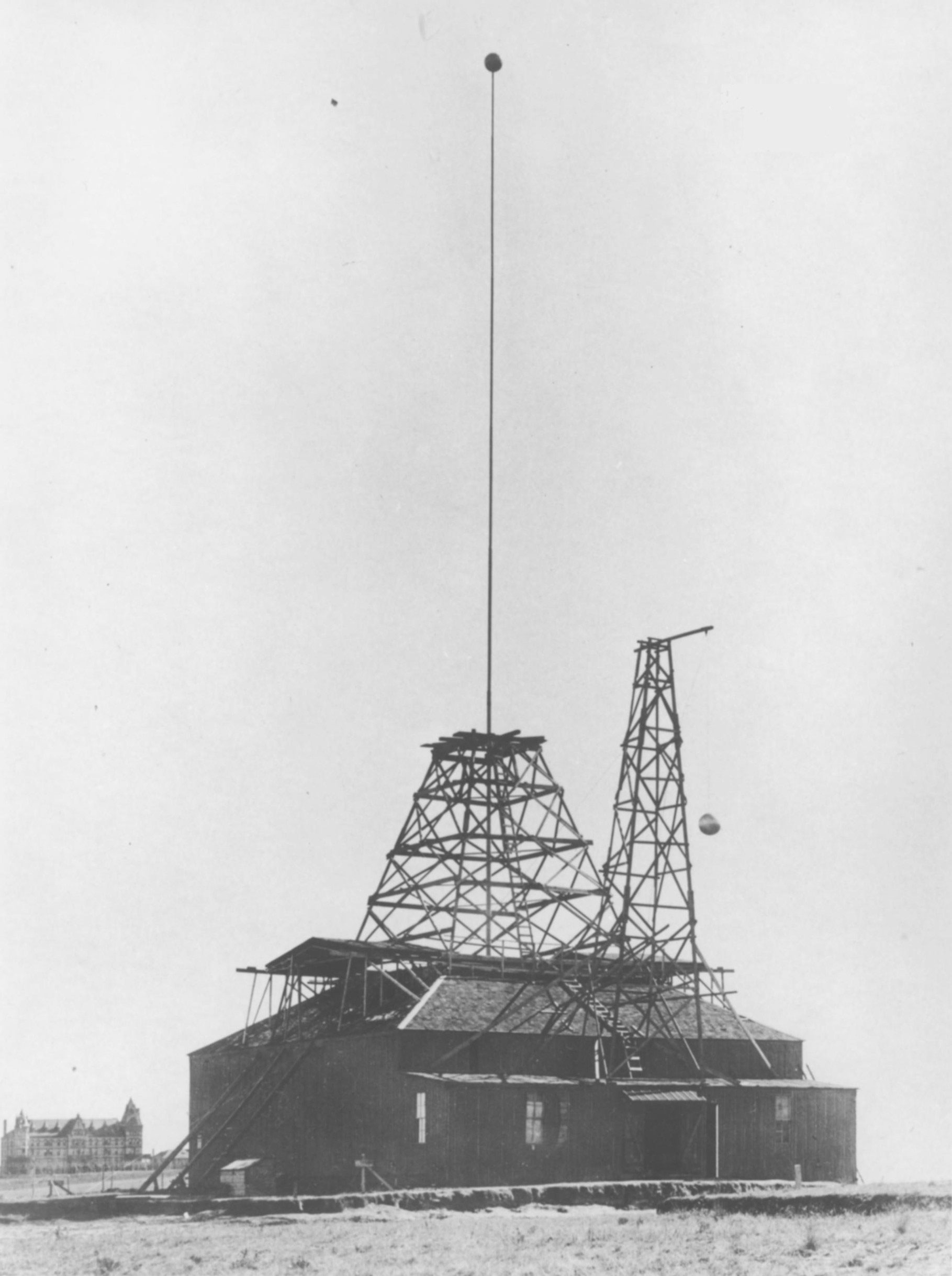
Steel pipes from 7 inches down to 2½ inches in diameter, shoved one into the next with a lap of two feet and four rivets at every joint. Lengths of pipe together 121 feet 9¾ inches, of which 7¾ inches are nipples. A dry fir pole, 10 by 10 inches, 19 feet 3 inches long. Total height from the ground to the bottom of the ball, the one foot from ground to floor included: 142 feet ¾ inch. The ball is hollow wood covered with tinfoil, 30 inches in diameter, its joints pressed in so that no point or edge stands out. Insulation of sheet rubber, tape, cord, shellac and weatherproof rubber paint; eight champagne bottles serve as insulators where the side beams meet the mast. Fig. 1 shows the station from the east, Pikes Peak behind it, the mast rising through the timber tower and the open roof.
Experiment No. 4
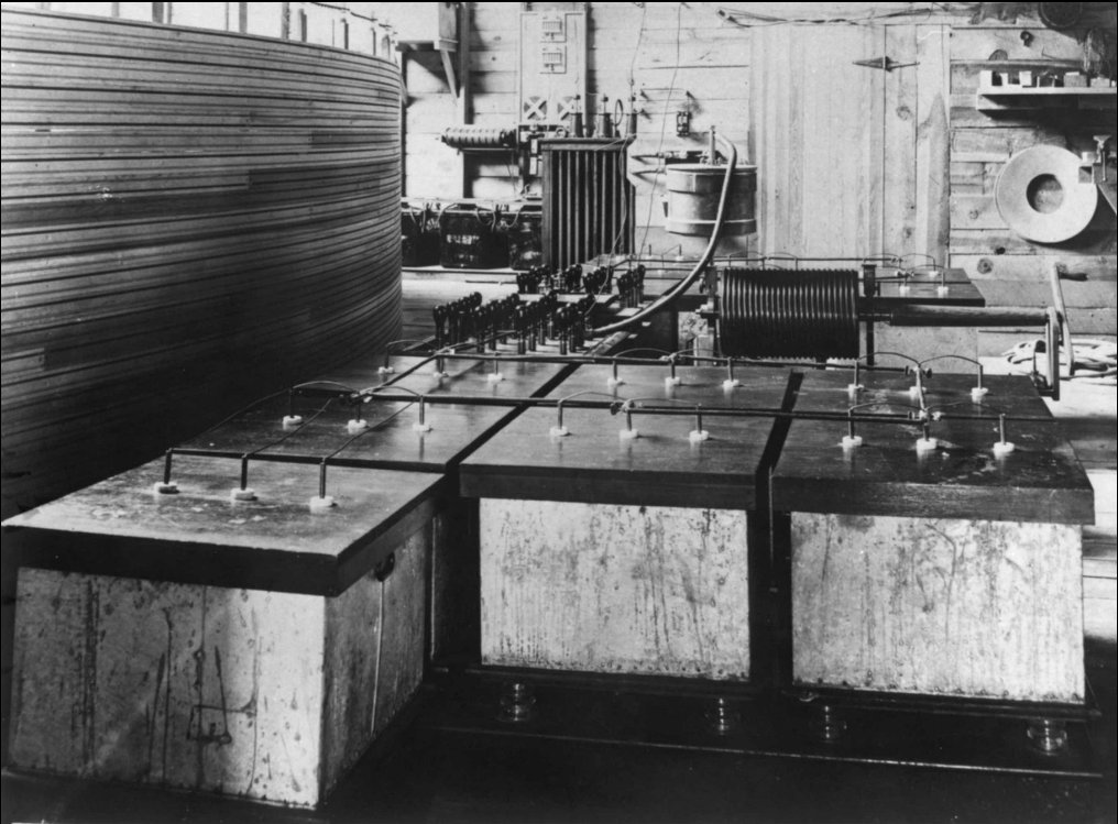
The great oscillator, as it stood in the first week of October. On the 1st I rewound the secondary with 22 turns, the last on porcelain insulators, with only one inch between turns: the coil could not withstand the strain and flashed over. On the 7th, with 14 turns, the series connection gave sparks of about twelve feet; rubber-covered No. 10 wire alone gave streamers reaching sometimes 16 to 18 feet; sparks to the ground passed over 16 feet, the curved paths about 24 feet. On the 11th I photographed a streamer of about 22 feet with a dark gap of one foot, some 25 feet in all, and the light was remarkably blue.
The wire inventory of the 8th, so that the numbers of the whole instrument stand together. Secondary: 803 metres, 17 turns of about 15 metres diameter each. Extra coil: 889 metres in 149 turns of about 1.9 metres each, and a special coil of 307 metres in 160 turns of about 0.61 metre. With connections, 2,030 metres of conductor from the earth plate to the terminal. Primary condensers: four tanks, 0.15264 microfarad.
Calculation
How much energy each discharge of the primary carries, and how fast it is spent.
- Four tanks, C = 0.15264 microfarad, charged to 30,000 volts (the Westinghouse transformer is reconnected for 22,500 or 30,000 volts): W = ½CV² = ½ × 0.15264 × 10⁻⁶ × (3 × 10⁴)² = 68.7 joules.
- The supply can deliver about 26 horsepower, or 26 × 746 ≈ 19,400 watts. One full charge takes 68.7 ÷ 19,400 ≈ 3.5 thousandths of a second; the supply can therefore fill the condensers fully about 280 times a second, whatever the break attempts.
- Suppose (an assumption) the primary rings at fifty thousand periods per second. A quarter of a period lasts 5 millionths of a second. If the condenser gives up its charge in that quarter, the rate of working is 68.7 ÷ 5 × 10⁻⁶ ≈ 13.7 million watts, or about 18,400 horsepower.
Reflection
Here is the difficulty I shall have with the public, set down honestly while I am alone with the figures. My plant draws a few tens of horsepower from the line, and on 25 July a five-minute run blew the fuse at an estimated twenty. Yet during the brief instant of each discharge the rate of working in my circuits rises to tens of thousands of horsepower, and with the energy piled up in a resonant secondary it may rise higher still. Both statements are true. When I write for the magazines I shall speak of the second, because it is the wonderful one. I note here that the measured streamers in this book are twenty-two to twenty-five feet. If I later describe discharges of sixty-five feet or more than a hundred, the reader should know which notebook to trust.
Margin
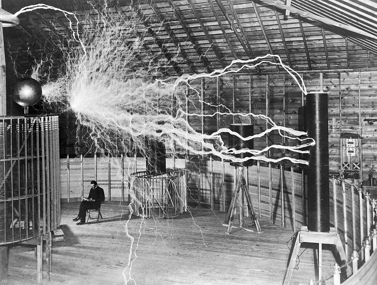
Written in December. Mr. Alley, the photographer, has made the picture the newspapers will love: myself seated reading beside the coil while sparks fill the air around me. It is two exposures on one plate. The discharges were photographed in the dark with the room empty; then the plate was exposed again with the machine silent and myself in the chair. No man could read by that light and keep his notes, or his hair.
Problems I set myself
1. The ball of 6 September is 30 inches in diameter and is said to stand at three million volts. Find its capacity in centimetres and in picofarads, the charge it holds, the energy stored in its field, and the electric force at its surface.
Answer. Radius r = 38.1 cm, so C = 38.1 cm. In farads, C = 4πε₀r = 4π × 8.854 × 10⁻¹² × 0.381 = 42.4 pF. Charge Q = CV = 42.4 × 10⁻¹² × 3 × 10⁶ = 1.27 × 10⁻⁴ coulomb, or 127 µC. Energy W = ½CV² = ½ × 42.4 × 10⁻¹² × 9 × 10¹² ≈ 191 J. Surface force E = V/r = 3 × 10⁶ ÷ 0.381 ≈ 7.9 × 10⁶ V/m. Air at sea level begins to break down near 3 × 10⁶ V/m, and in the thin air of the plateau at less. The ball could not hold three million volts quietly: it was streaming, which is exactly what I saw.
2. A tuned coil whose effective capacity is 189 cm rings at 245,500 periods per second. When an unknown body is connected to its free end, resonance moves to 231,000. What is the capacity of the body?
Answer. ΔC = C₀[(n₁/n₂)² − 1] = 189 × [(245,500/231,000)² − 1] = 189 × [(1.0628)² − 1] = 189 × 0.1295 ≈ 24.5 cm, or about 27 pF. That is roughly the capacity of the 18 inch ball, whose radius is 22.9 cm, with a short lead.
3. On 6 October the secondary of 16 turns, fed at p = 880 per second, took 13.8 amperes at 122.5 volts and had a resistance of 2.804 ohms. If the measurement were repeated at p = 440, what current would flow at the same pressure?
Answer. From the entry, pL = 8.423 Ω at p = 880, so L = 0.00957 H. At p = 440, pL = 4.21 Ω. Z = √(2.804² + 4.21²) = √(7.86 + 17.73) = √25.59 = 5.06 Ω. I = 122.5 ÷ 5.06 ≈ 24.2 A. Halving the frequency halves the reactance but leaves the resistance; the current does not quite double.
To the student who reads this later
You have instruments I would have given years of my life for, and a notation that would have saved me a hundred pages. Let me tell you what your century made of my extra coil.
First, the units. My centimetre of capacity is the Gaussian unit: in your International System, 1 cm of capacity = 4πε₀ × 1 cm ≈ 1.113 pF. My centimetre of self-induction is 1 nanohenry, so 10⁹ cm is one henry. A sphere's capacity, C = 4πε₀r, is the formula that made the ball of 38.1 cm so convenient: in my units the radius is the capacity.
Second, the coil. You would describe my extra coil as a helical resonator, a transmission line of distributed inductance and capacitance wound into a helix, shorted to ground at one end and loaded at the other. In phasor form the standing wave along it is V(z) = V₀ sin βz and I(z) = I₀ cos βz, with β = ω/v, the voltage and current a quarter period apart, exactly as Plate XVII draws them. With a top capacitance C_t the resonance condition becomes tan βℓ = 1/(ωC_tZ₀), where Z₀ is the line's characteristic impedance. Writing θ = βℓ and C_d for the total distributed capacitance of the line, this is θ tan θ = C_d/C_t, which the plate solves: a large top load drives θ below π/2 and lowers the frequency, and in the limit the coil becomes a simple lumped inductor resonating with the ball, ω² = 1/(LC_t).
Third, a correction. I treated the wire length as the quarter wave, travelling at the speed of light. That is only an approximation. The wave on a helix travels along its axis at a speed set by its pitch and diameter and by the coupling between turns, and the wire length of a real quarter-wave helical coil can differ considerably from a quarter of the free-space wave. Your engineers found better formulas for the self-capacitance of a single-layer coil (R. G. Medhurst published a much-used one in 1947) and simulate such coils exactly today. My rule gave the right order and, with the measurements of resonance I always made, the right tuning.
Fourth, honesty about my numbers. The figures in this notebook (streamers of 22 to 25 feet, three million volts estimated at a 38 cm ball, a supply of some twenty-odd horsepower) are the ones a careful student should cite. The larger figures in my magazine articles of 1900 are claims, and the photograph of me reading among the sparks is a double exposure.
What to try in a laboratory today, safely: wind 400 turns of fine enamelled wire on a tube 10 centimetres across, ground one end, and drive the coil weakly at its base from a signal generator through a small resistance. Watch the top with an oscilloscope probe held a short distance away, and sweep the frequency until the response peaks, in the megahertz range for a coil of that size. Add a small metal sphere to the top and measure the shift; from it compute the sphere's capacity by the resonance method of my October entry, and compare it with 4πε₀r. Do not try to make sparks. A small coil at resonance can still deliver a dangerous burn, and the patience of the measurement is the whole lesson.
If you would like to ask me how it felt to sweep that regulating coil in the dark until the ball began to hiss, come and ask me.
Sources and liberties
The Tesla Notes are a modern reconstruction written in Nikola Tesla's voice by Eternal Gardens. Dates, patents, lectures, apparatus and quotations come from the sources below; the private reflections, the order of the working and the sketches are ours.
- N. Tesla, Colorado Springs Notes, 1899 to 1900, ed. A. Marinčić and V. Popović (Belgrade: Nolit, 1978), page images: Tesla Universe, from p. 25; the mast entry of 17 October 1899: p. 226
- The same notes transcribed by month, with the editors' introduction: bibliotecapleyades.net, Colorado Springs Notes
- N. Tesla, "The Transmission of Electric Energy Without Wires", Electrical World and Engineer, 5 March 1904: PBS transcription
- N. Tesla, "The Problem of Increasing Human Energy", Century Magazine, June 1900: Wikisource
- PBS, "Tesla: Life and Legacy, Colorado Springs": pbs.org
- "Tesla Experimental Station", for the site and its fate: Wikipedia
- R. G. Medhurst, "H.F. Resistance and Self-Capacitance of Single-Layer Solenoids", Wireless Engineer, February and March 1947, as cited in the Tesla Coil Mailing List archive: pupman.com; on helical resonators generally: Wikipedia, "Helical resonator"
- Photographs: laboratory exterior, primary circuit, the double exposure, all public domain on Wikimedia Commons
Arrival is given as 17 or 18 May 1899 in different sources; we use the 18th. Colonel Astor's support is given as $30,000 or $100,000, so we name no figure. The mast is 142 feet ¾ inch to the bottom of a wooden ball covered in tinfoil, as in the entry of 17 October, not the 200 feet and copper ball of popular accounts. The voltages in the notebook are Tesla's own estimates, and the discharges of 65 and over 100 feet are his public claims of 1900, never measured in the notebook. The calculations of 3 July and 7 September are reworked here from his stated constants, and the small differences from his entered figures are noted where they occur. The density correction of 18 May, the energy-per-discharge estimate, the image-method margin and the assumed fifty thousand periods are our reconstruction.