





New York, the winter of 1886 to 1887. I write this by a kerosene lamp in a rented room, with the clay of a Western Union trench still under my nails, and I copy into a clean book the loose sheets I kept at Rahway. They are about one machine that is not mine: the converter, the coil of two windings on one body of iron that the English call a secondary generator and the Hungarians now call a transformer. It has no moving part and it turns a thousand volts into fifty as quietly as a sum is carried in the head. Everybody who understands it says the same thing: it works only with alternating current. I want to know exactly why, to the last turn of wire, because the man who owns the converter and the man who owns a motor for alternating current will between them own the future of electric power, and at present I own a shovel.
"In order to obtain rapid variations in the strength of the current, essential to efficient induction, a great number of undulations are employed. From this practice various disadvantages result."
Nikola Tesla, "A New System of Alternate Current Motors and Transformers", American Institute of Electrical Engineers, May 1888
Rahway, 12 November 1885. The secondary generator of Gaulard and Gibbs
The journals have the account of the Turin exhibition of last year. Lucien Gaulard, a Frenchman, and John Dixon Gibbs, an Englishman, took current from an alternating machine at Turin, sent it out along a line to Lanzo and back, some forty kilometres of wire, and at stations along the way lit lamps through their secondary generators. Each of these is an induction coil with a core that is open at both ends: a straight bundle of iron with two windings upon it. The primaries of all the stations are strung in series along the line, like beads on a thread, and the lamps of each station hang on its secondary.
The arc lamps on Irving Street here run on my own dynamos with commutators, and I am proud of them. But I have read the Turin account four times. The line carries a high pressure and a small current, and the work is done at the far end at a low pressure and a large current. That is the whole art of distant distribution in one sentence, and Edison's men in New York, with their 110 volts and their copper mains as thick as a wrist, do not possess it.
Calculation
Let me set down the principle as Faraday left it, in the plainest form. When the magnetic lines threading a circuit change, a pressure is set up in the circuit proportional to the rate of change. If the same lines Φ thread every turn of a coil of N turns, the turns add like cells in series:
e = −N dΦ/dt
- Put two coils on one core: N₁ turns on the primary, N₂ on the secondary.
- If every line that threads the primary also threads the secondary, then at every instant the same dΦ/dt acts on both.
- So e₁ = −N₁ dΦ/dt and e₂ = −N₂ dΦ/dt at the same instant.
- Divide: dΦ/dt cancels, and with it the iron, the frequency and the shape of the wave.
e₁ / e₂ = N₁ / N₂
The ratio of pressures is the ratio of turns, and nothing else enters. A converter with 700 turns on the primary and 35 on the secondary makes 50 volts out of 1,000 because 700 is twenty times 35. It holds only on the condition of step 2: every line must thread both coils.
Margin
That condition is exactly what the open core of Gaulard and Gibbs does not satisfy. In a straight bundle the lines come out of one end, spread into the air and return outside. Many lines that thread the primary turn back before they reach the secondary. The ratio then depends on where the coils sit and on how much iron is pushed in, and I read that the inventors adjust the pressure by sliding the core in and out. A regulator that works by changing the leakage of lines is a confession that the lines are leaking. Faraday's own ring of 29 August 1831 was closed: two coils on a ring of soft iron. He had the better form half a century ago and used it only to see a galvanometer needle jump.
Reflection
Series connection troubles me more than the open core. If the primaries are in series, the same current passes through every station. Switch off the lamps at one station and its secondary draws nothing; its primary then behaves as a bare coil of iron and wire, and it chokes the current for all the others. The stations are chained to one another's habits. A city cannot be lit like that. Each house must take what it wants from a main held at a steady pressure, as each house takes water.
Rahway, 18 April 1886. The closed ring of Budapest, and Mr. Stanley's lamps
Two pieces of news, and both of them sting.
The first is from Budapest, from the Ganz works, a few streets from the Telephone Exchange where I worked in 1881 and 1882. Three of their engineers, Zipernowsky, Bláthy and Déri, have closed the core. Their converters are built with the iron forming a complete path, either the iron enclosing the windings or the windings enclosing the iron, and they connect the primaries in parallel across the mains, each converter taking from a main held at a constant pressure. They delivered the first of these machines in the autumn of 1884, and they have patented the arrangement. Their name for it is the transformer. I walked those streets reciting Goethe while these men were winding coils.
The second is from Massachusetts. Mr. William Stanley, who works for George Westinghouse of Pittsburgh, lit the shops and offices along the main street of Great Barrington on 20 March with alternating current and converters of his own design. Westinghouse bought the American rights of Gaulard and Gibbs in February for fifty thousand dollars, I am told, and set Stanley to make the thing practical, since the Edison company holds an option on the Hungarian patents. Stanley's generator is a Siemens alternator in an old rubber mill, giving 500 volts. His wires run along the elm trees of the street to six converters in the cellars of the buildings, each lowering the pressure to 100 volts for the lamps. For a test he raised the 500 volts to 3,000 and brought it back down again. His converters are built of iron plates shaped like the letter E, and they are connected in parallel.
Calculation
If the ratio of pressures is the ratio of turns, what is the ratio of currents? I reason from the conservation of energy, the one law that never deserts me.
- In a perfect converter nothing is lost: the power going in equals the power coming out. V₁I₁ = V₂I₂.
- Then I₁ / I₂ = V₂ / V₁ = N₂ / N₁. The currents go in the inverse ratio of the turns.
- Rewrite: N₁I₁ = N₂I₂. The ampere-turns of the primary equal the ampere-turns of the secondary.
Step 3 is the more illuminating form, because it tells me what the iron feels. The secondary current, by Lenz's law, always opposes the change that produces it, so its ampere-turns push against the primary's. The iron sees the difference, and in a good converter the difference is almost nothing. The primary current rises with the load exactly enough to cancel the secondary's opposition and keep the flux what the applied pressure demands. A converter is a balance of two opposed magnetising forces with a small remainder.
Now a calculation for Stanley's shops, with my own guesses for the lamps. Converter ratio 500 to 100, so 5 : 1. Let a shop burn ten lamps of sixteen candles, each taking about half an ampere at 100 volts.
- Secondary current I₂ = 10 × 0.5 = 5 amperes.
- Primary current I₁ = I₂ × N₂/N₁ = 5 / 5 = 1 ampere.
- Resistance of the lamp group: R = 100 / 5 = 20 ohms.
- Seen from the primary, this group looks like a resistance R′ = V₁/I₁ = 500 / 1 = 500 ohms.
And 500 = 20 × 5². So the general rule:
R′ = (N₁/N₂)² R
The converter multiplies resistance by the square of the ratio of turns. To the mains the ten hungry lamps look like one modest resistance of 500 ohms, and the copper of the line need only be sized for one ampere.
Margin
Stanley's 4,000 feet of line at 500 volts lose, I hear, about two per cent. Had he sent the same power at 100 volts, five times the current would flow, and the loss, going as the square of the current, would be twenty-five times as great: half the power would be spent warming the elms. This is the arithmetic of copper I worked out at Edison's in 1884, and here it is with a remedy attached.
Reflection
The Hungarians may keep their ring and Stanley his street with my blessing. The year I have lost is what I grudge. The converter needs alternating current, and alternating current today has no motor; it can light lamps and that is all. Every central station that buys converters is building a road that my motor could travel. I have the motor complete in my mind since 1882 and I built it once with my own hands at Strasbourg. What I lack is a room, a lathe and somebody with money who will watch it turn.
New York, 9 February 1887. Why the converter refuses a steady current
The ground is frozen and we break it with picks before the shovels can bite. I do the following calculation in my head in the trench, and write it out at night.
Connect a converter to a battery. At the moment of closing, the current rises, the flux rises, and the secondary gives a kick. Then the current settles to the value fixed by the resistance of the primary, the flux stands still, dΦ/dt is zero and the secondary is dead. Worse, the primary of a converter is wound with few ohms, because it is meant to be held back by its self-induction and by nothing else. On a steady pressure it is very nearly a short circuit. A 1,000-volt converter with a primary of five ohms would draw two hundred amperes and burn. The converter lives on change, and a steady current gives it none.
Calculation
Let the applied pressure be a sine, and ask what flux it compels. If the windings lose little, the pressure set up by the changing flux must almost exactly balance the pressure applied, at every instant:
- v₁ = N₁ dΦ/dt (the sign is a matter of which way I wind).
- Let Φ = Φₘ sin ωt, where ω = 2πf and f is the number of periods in a second.
- Then v₁ = N₁ ω Φₘ cos ωt. The pressure is greatest when the flux passes through zero, and the flux is greatest when the pressure is zero: the flux lags the pressure by a quarter of a period.
- The crest of the pressure is N₁ ω Φₘ = 2π f N₁ Φₘ.
- The instruments that heat a wire, such as Cardew's voltmeter, read a smaller number than the crest. For a sine wave the reading is the crest divided by √2. (I take this for now from the instrument makers; I shall prove it properly one day.)
- So the effective pressure is V₁ = (2π/√2) f N₁ Φₘ.
And 2π/√2 = 4.4429. This is the rule every builder of converters must carry in his pocket:
V = 4.44 f N Φₘ
In the units of the electricians, with Φ counted in lines of force, the practical volt being 10⁸ absolute units, it reads V = 4.44 f N Φₘ / 10⁸.
Now let me design. I want 1,000 volts on the primary at 16,000 alternations a minute, which is 133⅓ periods a second, the figure I hear Westinghouse's alternators give. The core is to have a cross-section of 40 square centimetres, and I shall not drive the iron beyond 6,000 lines to the square centimetre, which is about 0.6 of the modern tesla, for above that the iron grows hot and the magnetising current climbs.
- Φₘ = 6,000 × 40 = 240,000 lines (0.0024 weber).
- N₁ = V × 10⁸ / (4.44 × f × Φₘ) = 10¹¹ / (4.44 × 133.33 × 240,000).
- Denominator: 4.44 × 133.33 = 592.0; × 240,000 = 1.4208 × 10⁸.
- N₁ = 10¹¹ / 1.4208 × 10⁸ = 703.8. Take 704 turns.
- Check: 4.44 × 133.33 × 704 × 240,000 / 10⁸ = 1,000.2 volts.
- For lamps of 50 volts, N₂ = 704 × 50 / 1,000 = 35.2. Take 35 turns.
So the turns are fixed by four things only: the pressure, the frequency, the area of iron and the density of lines I dare. About 0.7 of a turn for every volt, at this frequency and this core. Halve the frequency and I must double the turns or double the iron. That remark will matter later; I underline it.
Calculation
The magnetising current. Even good iron needs some ampere-turns to drive the flux round the ring, and these must come from the primary even when no lamp is lit. Treat the primary alone as a coil of self-induction L wound on a closed path of length l and section A, with the permeability of the iron µ:
- L = µ N₁² A / l.
- For my core, l = 60 cm, A = 40 cm², and good soft iron multiplies the effect of air by about 2,000 at this flux density. In modern units µ = 2,000 × 4π × 10⁻⁷.
- L = 2,000 × 1.2566 × 10⁻⁶ × 700² × 0.004 / 0.6 = 8.2 henrys, if I use 700 turns.
- The opposition of this coil to a sine current is ωL = 837.8 × 8.2 = 6,870 ohms. (I shall make this "spurious resistance" the subject of a proper entry when I have time.)
- Magnetising current = 1,000 / 6,870 = 0.145 ampere, lagging the pressure by a quarter period.
A seventh of an ampere, against two amperes at full load of forty lamps, and it does no work: it goes in and comes out again each half period, like breath.
Draftsman's note
I have drawn the converter as Plate V and made it work. The core is a closed rectangle of thin plates. Blue turns on the left limb are the primary, red turns on the right the secondary; the violet arrows show the flux going round, swelling, shrinking and reversing. The lamps hang at the right. Below, the waves: pressure v₁ in black, flux Φ dashed, primary current i₁ in blue and secondary pressure v₂ in red. Move the lamps to zero and watch i₁ shrink to the magnetising current and slip a quarter period behind the pressure; add lamps and see it grow and swing into step. Then take the primary turns down below two hundred and watch the iron saturate.
Margin
Saturation is the converter's warning against greed. If I wind only 200 turns, the same 1,000 volts demands 3.5 times the flux, 2.1 tesla, and no iron I know will carry it. The permeability collapses, L collapses, and the magnetising current rises without limit. The flux is set by the pressure; the iron does not get a vote.
New York, 2 March 1887. Iron that heats itself
Sunday, no digging. I borrowed a cheap induction coil from a man at the cable office and ran it on the alternating current of a small machine at the works where he took me. I put my hand on a solid iron bar placed across its poles, and in a minute the bar was warm. The coil's own core, a bundle of varnished wires, stayed cool. The bar has no winding on it, no current is led into it, and yet it heats. It heats because it is a conductor sitting in a changing flux. Every loop I could imagine drawn inside the bar is a closed circuit, and each loop has a pressure set up in it by the changing lines it encloses. The bar is full of whirling currents. These are the eddies of Foucault, who showed in 1855 that a copper disc spun between magnet poles grows hot.
Experiment No. 1
Apparatus: the borrowed induction coil, a solid bar of soft iron 1 cm thick, a bundle of the same section made of iron plates half a millimetre thick with paper between them, a thermometer bound to each with cotton. Procedure: each piece across the poles for five minutes in turn, the same current. Result: the solid bar rose by some twenty degrees, the bundle by perhaps one. My thermometer is a poor one and the contact is uncertain, so I trust only the ratio, and the ratio is large.
Calculation
Why should thin plates make so great a difference? Let me find the law.
- Take a plate of thickness t, much wider and longer than it is thick, with the flux density B running along its length, uniform across it (true when the plate is thin), and B = Bₘ sin ωt.
- Measure x across the thickness from the middle plane, so x runs from −t/2 to +t/2. By symmetry no eddy flows along the middle plane.
- Take a thin loop in the plate, running along its width at +x and back at −x. It encloses flux 2x × b × B, where b is its width. Faraday gives a pressure 2xb dB/dt round it.
- The path length is about 2b, so the electric force along the loop is the pressure divided by the path: E = x dB/dt.
- The current density is J = σE = σx dB/dt, with σ the conductivity of the iron.
- Heat per unit volume per second at depth x: J²/σ = σx² (dB/dt)².
- Average over the thickness: (1/t) ∫ x² dx from −t/2 to t/2 = (1/t)[x³/3] = (1/t)(t³/24 + t³/24) = t²/12.
- So the heat per unit volume is σ (dB/dt)² t²/12.
- Now (dB/dt)² = ω² Bₘ² cos² ωt, whose average over a period is ½ω²Bₘ².
p = σ ω² Bₘ² t² / 24 per unit volume.
Four things in it: the conductivity of the iron, the square of the frequency, the square of the flux density, and the square of the thickness. The last is the one the builder controls. Halve the thickness of the plates and the eddy loss falls to a quarter.
Numbers for my converter: iron of resistivity about ten microhm-centimetres, so σ = 10⁷ in modern units; ω = 837.8; Bₘ = 0.6 tesla; t = 0.5 mm.
- ω² = 7.02 × 10⁵.
- σω² = 7.02 × 10¹²; × Bₘ² (0.36) = 2.53 × 10¹²; × t² (2.5 × 10⁻⁷) = 6.32 × 10⁵.
- Divide by 24: p = 26,300 watts per cubic metre.
- Iron weighs 7,800 kg to the cubic metre, so the loss is 3.4 watts per kilogram.
My core of 40 cm² and 60 cm mean path holds 2,400 cubic centimetres, about 18.7 kg of iron, which costs some sixty watts in eddies alone at 133⅓ periods. A converter of two kilowatts that throws away three per cent of its rating heats the cellar day and night, loaded or empty.
Margin
Here the formula lies to me, and I must say how. Put t = 1 cm for the solid bar and it gives 400 times the loss, 1,350 watts per kilogram, which would melt it. The bar did not melt. The reason is that step 1 assumed the flux uniform across the thickness. In a thick bar the eddies themselves oppose the change of flux in the interior, so the lines crowd into a thin skin near the surface and the heart of the bar carries almost nothing. The thick core is wasteful twice over: it heats, and it does not even carry the flux. Thin plates, insulated from one another, cut every great eddy into many small ones and let the flux fill the iron.
Margin
There is a second loss that no lamination will cure. Professor Ewing has measured how iron, carried round a cycle of magnetisation, returns less work than was put into it; he calls the lag hysteresis. The lost work per cycle is the area of his loop, so this loss grows as the frequency itself, while the eddy loss grows as its square. At high frequency the iron is cheap in quantity and expensive in heat. I put this beside the note I underlined above.
Draftsman's note
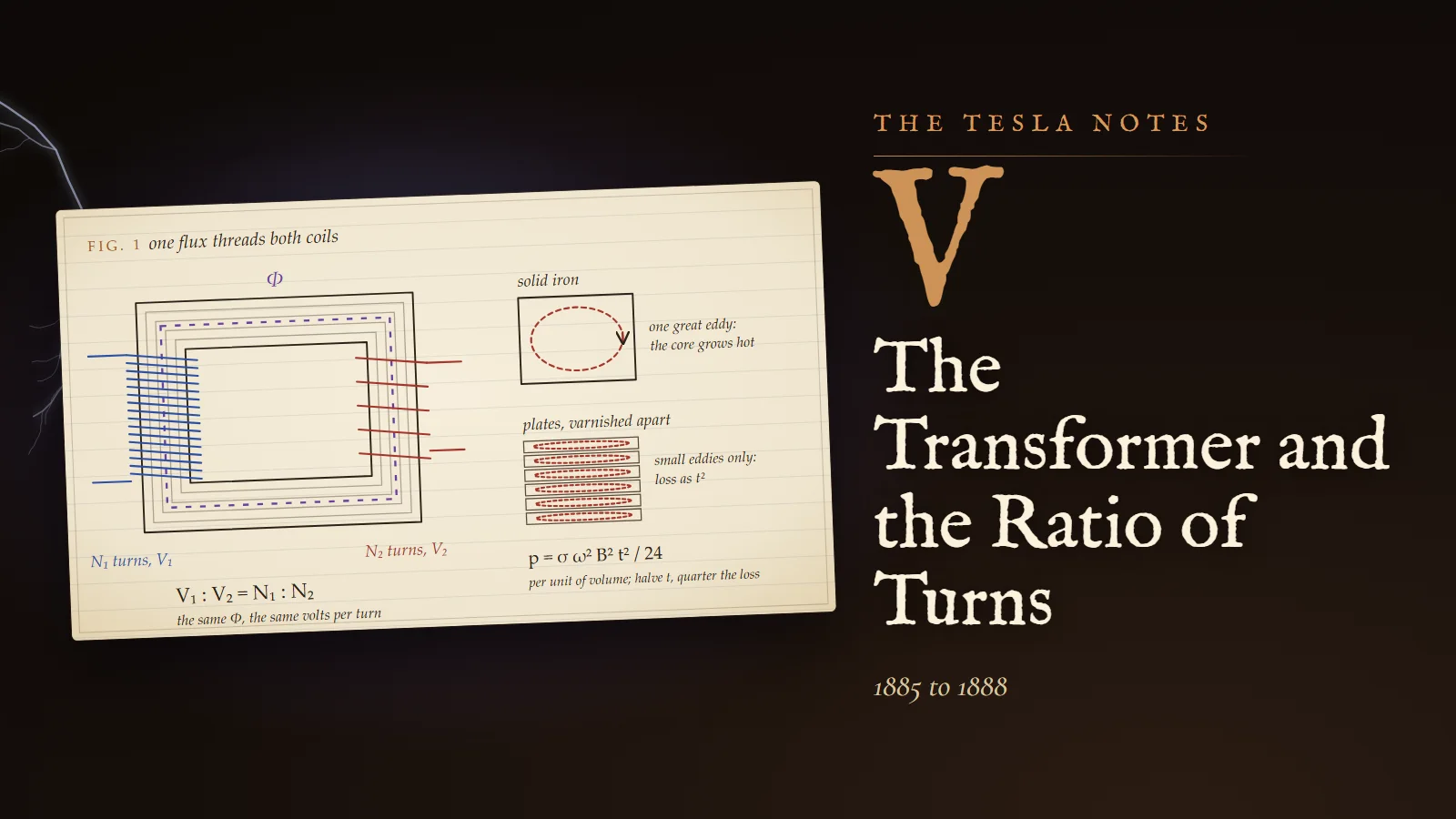
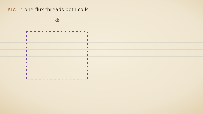
Fig. 1 shows the closed core as I would build it: a rectangle of plates, each about half a millimetre, varnished or papered apart, with the joints of alternate layers overlapped so the lines need not cross an air gap. Primary of many fine turns on the left limb, secondary of few thick turns on the right. On the right of the sheet, the same piece of iron solid and laminated, with the eddies drawn as I imagine them.
Reflection
We finished a length of trench on Broadway at dusk and I stood a minute watching the arc lamps come on along the avenue, each one a little sun hissing on its pole. Mr. Brown, the Western Union superintendent who oversees our gang, asked me what I was looking at so hard. I told him I was calculating how much copper the city wastes every night. He did not laugh, which is more than I can say for most men I have told. He asked whether I had ever thought of putting my ideas before people with capital. I said I had thought of nothing else for five years.
89 Liberty Street, 23 December 1887. A converter whose poles go round
Everything has changed since the spring. Mr. Alfred Brown of Western Union brought Mr. Charles Peck, a lawyer of Englewood, and in April they formed the Tesla Electric Company to give me a laboratory. It is a floor at 89 Liberty Street, above a printer, near enough to the Edison offices that I pass them every morning. The printer's engine drives my machines at night when his presses stop. I have built the motors exactly as I saw them in 1882, and in October I filed the first of my applications. Today I file another: a system of distribution with converters of a new kind.
The idea is this. In every converter I have described, the flux in the core swells, collapses, reverses and swells again. Twice in every period it passes through zero, and at those instants the core is idle and does nothing. Now take a closed ring of laminated iron, as in my motor, and wind on it two pairs of primary coils fed from the two circuits of my two-phase generator, the currents a quarter period apart. The ring then carries a magnetic pole that travels round it without stopping, exactly the field that drives my motor. Wind secondary coils anywhere on the ring. As the poles pass, each secondary is cut by lines that are always changing at full rate. The ring is never idle.
Calculation
Prove that a secondary anywhere on the ring receives the same pressure.
- The two primary pairs produce, in the iron under a point at angle θ round the ring, flux contributions proportional to cos θ cos ωt and sin θ sin ωt, the coils being set a quarter of the ring apart and the currents a quarter period apart.
- Add them: cos θ cos ωt + sin θ sin ωt = cos(ωt − θ).
- So the flux through a secondary placed at θ is Φ(θ, t) = Φₘ cos(ωt − θ). Its magnitude Φₘ is the same for every θ; only its timing depends on position.
- The pressure induced in a secondary of N₂ turns at θ is e = −N₂ ∂Φ/∂t = N₂ ω Φₘ sin(ωt − θ).
Every secondary sees the full crest N₂ωΦₘ. Its phase is simply its angle round the ring. A secondary at 0° and one at 90° give currents a quarter period apart: the converter can feed two-phase motors at the far end directly, or I can take ordinary single-phase current from any one coil.
Margin
Written in May 1888, after the lecture: I put this argument to the Institute in these words, and I copy them here so that I do not later improve them in memory. "In producing a shifting of the poles in the transformer, and thereby inducing currents, the induction is of the ideal character, being always maintained at its maximum action. It is also reasonable to assume that by a shifting of the poles less energy will be wasted than by reversals."
Experiment No. 2
Apparatus: a ring of sheet-iron plates, 20 cm outside diameter and 12 cm inside, 4 cm deep; two primary pairs of 120 turns each of number 16 wire; four secondaries of 30 turns at 0°, 45°, 90° and 135°; my two-phase generator at a low speed from the printer's engine; a Cardew voltmeter borrowed by Mr. Peck. Procedure: read each secondary in turn on open circuit, then with a bank of lamps. Result: on open circuit all four read alike within the error of the instrument, and the ratio of primary to secondary pressure was four to one, as 120 to 30 requires. Under load the readings fell by a few per cent, the fall I expected from the resistance of the coils and the lines that leak between them. A secondary at 45° gives a current intermediate in phase between those at 0° and 90°, which I proved with a pair of telephone receivers, one to each ear, hearing the two hums come and go together and apart as I switched.
Reflection
A sceptic would say that I have built a converter more complicated than the Hungarians' to do the same thing. He would be partly right. A single-phase converter on a single-phase line is simpler, and I do not pretend otherwise. But a converter whose field turns belongs to the same family as my motor and my generator. It is one system: generator, line, converter and motor all built on the same moving pole, and I want it to exist with an intensity that keeps me awake.
Tonight the printer's engine stopped at midnight and I sat in the dark of the laboratory with the ring still warm, thinking of the Turin line and the Great Barrington elms, and of how the converter has been ready and waiting all these years for its partner. Alternating current has carried light. It must now learn to carry work.
Problems I set myself
1. A converter is to step 2,000 volts down to 100 volts at 133⅓ periods per second, on a core of 50 square centimetres worked at a crest density of 0.6 tesla (6,000 lines per square centimetre). Find the primary and secondary turns.
Answer. Φₘ = 0.6 × 0.005 = 0.003 weber. N₁ = V / (4.44 f Φₘ) = 2,000 / (4.44 × 133.33 × 0.003) = 2,000 / 1.776 = 1,126 turns. N₂ = 1,126 × 100 / 2,000 = 56.3, so 56 turns, which gives 99.5 volts; take 57 turns if the lamps must have a little more to allow for the fall under load.
2. Forty lamps of 50 volts and 1 ampere hang on the secondary of a 1,000 : 50 converter. Find the secondary and primary currents, and the resistance the lamps present as seen from the primary mains.
Answer. The ratio is 20 : 1. I₂ = 40 × 1 = 40 amperes; I₁ = 40 / 20 = 2 amperes. The lamps in parallel are 50/40 = 1.25 ohms; seen from the primary they are (20)² × 1.25 = 500 ohms. Check: 1,000 / 500 = 2 amperes.
3. My core loses 3.4 watts per kilogram in eddies with plates 0.5 mm thick at 133⅓ periods and 0.6 tesla. What would it lose with plates 0.35 mm thick at 60 periods and the same density?
Answer. Eddy loss goes as t²f². The thickness factor is (0.35/0.5)² = 0.49; the frequency factor is (60/133.33)² = 0.2025. The loss becomes 3.4 × 0.49 × 0.2025 = 0.34 watt per kilogram, a tenth of the first. But at 60 periods the same pressure on the same turns needs 133.33/60 = 2.22 times the flux, so to keep 0.6 tesla the core must have 2.22 times the section. There is no free gift in the frequency.
To the student who reads this later
You will write my first calculation as Faraday's law in its integral form, ∮ E · dl = −dΦ/dt, and you will call my converter by the Hungarian name, transformer, which won. You will learn the ideal transformer in three lines, V₁/V₂ = N₁/N₂, I₁/I₂ = N₂/N₁, Z′ = (N₁/N₂)² Z, and then the equivalent circuit that Charles Steinmetz made standard in the 1890s: series resistances and leakage reactances for each winding, a shunt branch for the magnetising reactance and the core loss. That is precisely the model I wrote into Plate V, with numbers chosen to be honest for a converter of 1887.
The formula V = 4.44 f N Φₘ is still on the first page of every transformer designer's notebook. The "crowding of the lines into a skin" that I described for the thick bar is the skin effect: for a sine wave, current and field penetrate a conductor only to a depth δ = √(2/(ωµσ)). For iron with a relative permeability of 1,000 at 133⅓ periods that depth is about 0.44 mm, which is why plates of half a millimetre were already near the useful limit, and why plates thinner still are used at higher frequencies. Steinmetz gave the empirical law of hysteresis loss, proportional to f times B to the power 1.6, in 1892. Silicon steel (from Hadfield's work around 1900) and then grain-oriented steel (Goss, 1934) cut core losses many times over, and large modern power transformers exceed 99 per cent efficiency.
I must be honest about the rotating-field converter of my 23 December entry. It was correct physics, and patent 381,970 is a real claim, but it did not displace the ordinary single-phase transformer. A reversing flux is perfectly serviceable; iron carried round by a rotating field suffers its own "rotational" hysteresis, and the simplicity of the single-phase transformer won every argument of cost. My hope that shifting poles would waste less energy than reversals was a reasonable guess that later measurement did not reward. The system I believed in, generator, line, converter and motor all polyphase, did come true, but with ordinary transformers on each phase.
To try in a laboratory today: wind two coils on a laminated core salvaged from a mains transformer, drive the primary from a signal generator through a small audio amplifier at a few volts, and measure the ratio with an oscilloscope. Then remove the load and watch the primary current fall and slide toward a quarter period behind the voltage. Never connect a home-wound coil to the mains.
If you would like to argue with me about Gaulard's open core, or ask what it felt like to read about Budapest while digging trenches in New York, come and ask me. I will answer as I am, a man of my century.
Sources and liberties
The Tesla Notes are a modern reconstruction written in Nikola Tesla's voice by Eternal Gardens. Dates, patents, lectures, apparatus and quotations come from the sources below; the private reflections, the order of the working and the sketches are ours.
- Nikola Tesla, "A New System of Alternate Current Motors and Transformers", AIEE, May 1888: Wikisource text.
- Nikola Tesla, "My Inventions", Electrical Experimenter, 1919: Wikisource.
- US Patent 381,970, System of Electrical Distribution, filed 23 December 1887, granted 1 May 1888: Google Patents; and US 382,282, Method of Converting and Distributing Electric Currents: Google Patents.
- IEEE Milestone, Alternating Current Electrification, 1886 (Great Barrington, 20 March 1886; 500 volts, 3,000-volt test, six step-down converters at 100 volts): ETHW.
- Edison Tech Center, "Great Barrington 1886" (4,000-foot line, E-shaped plates, Siemens alternator in Horace Day's rubber mill): edisontechcenter.org.
- "Transformer" and "ZBD transformer" (history sections: Gaulard and Gibbs at Turin 1884, Ganz delivery of September 1884, 1885 closed-core patents, Westinghouse's February 1886 purchase, Edison option): Wikipedia, Wikipedia; Grace's Guide on Gaulard and Gibbs: gracesguide.co.uk.
- W. Bernard Carlson, "Places of Invention: Nikola Tesla's Life in New York", Gotham Center, 2013 (ditch-digging under Alfred S. Brown, Brown and Peck, 89 Liberty Street): gothamcenter.org; and Carlson, Tesla: Inventor of the Electrical Age, Princeton University Press, 2013.
The Turin line length (about forty kilometres) and the date of the first London showing of Gaulard and Gibbs vary between sources. The Westinghouse frequency of 133⅓ periods is attested for 1888 by Tesla himself in "My Inventions"; Edison Tech Center gives it for Stanley's 1886 Siemens machine, which we treat as hearsay in the entry. The lamp currents, the core dimensions, the borrowed-coil experiment, the Broadway conversation and both experiments are our reconstruction; the numbers in them are worked to be physically right for apparatus of the period.