




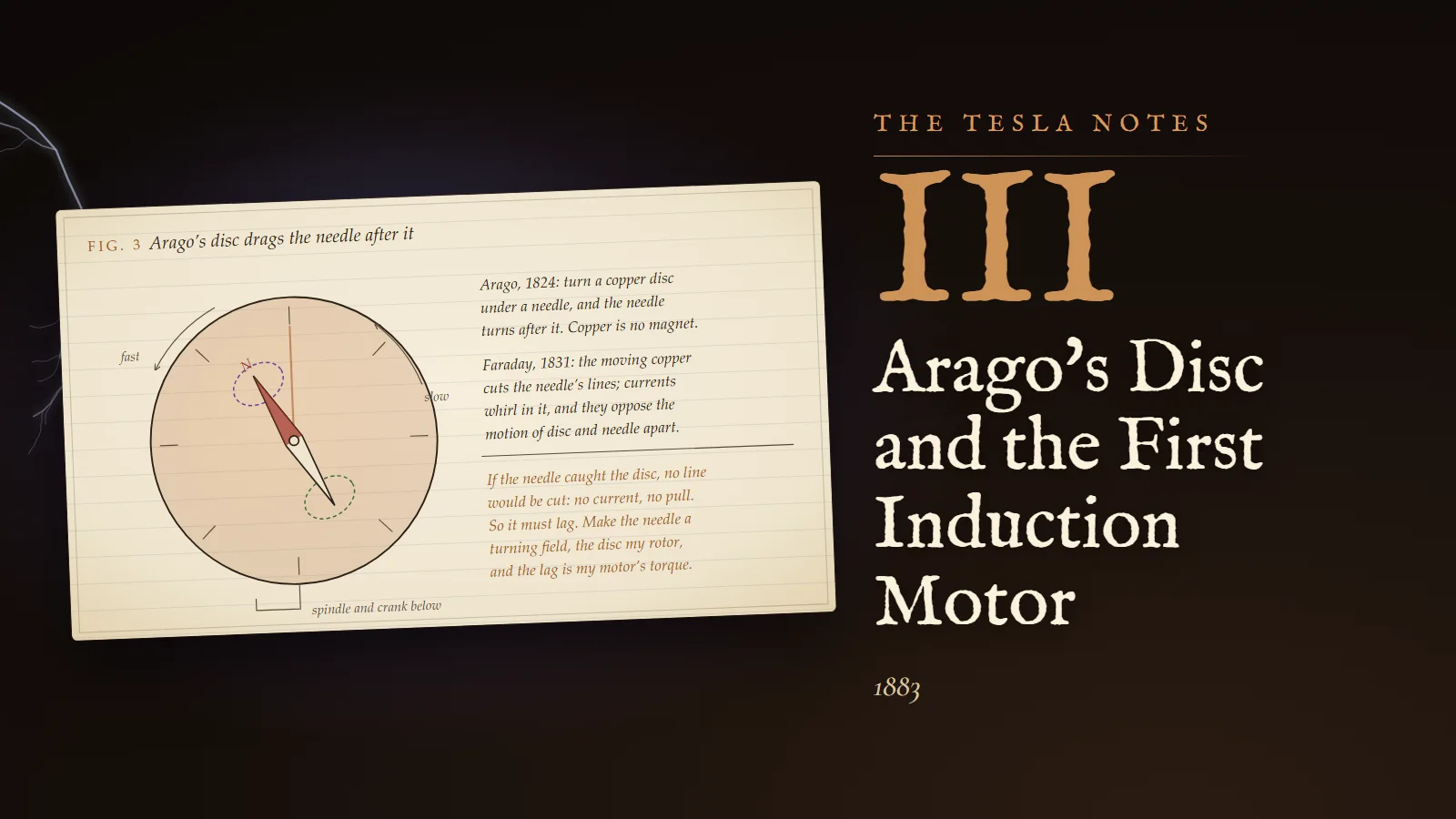

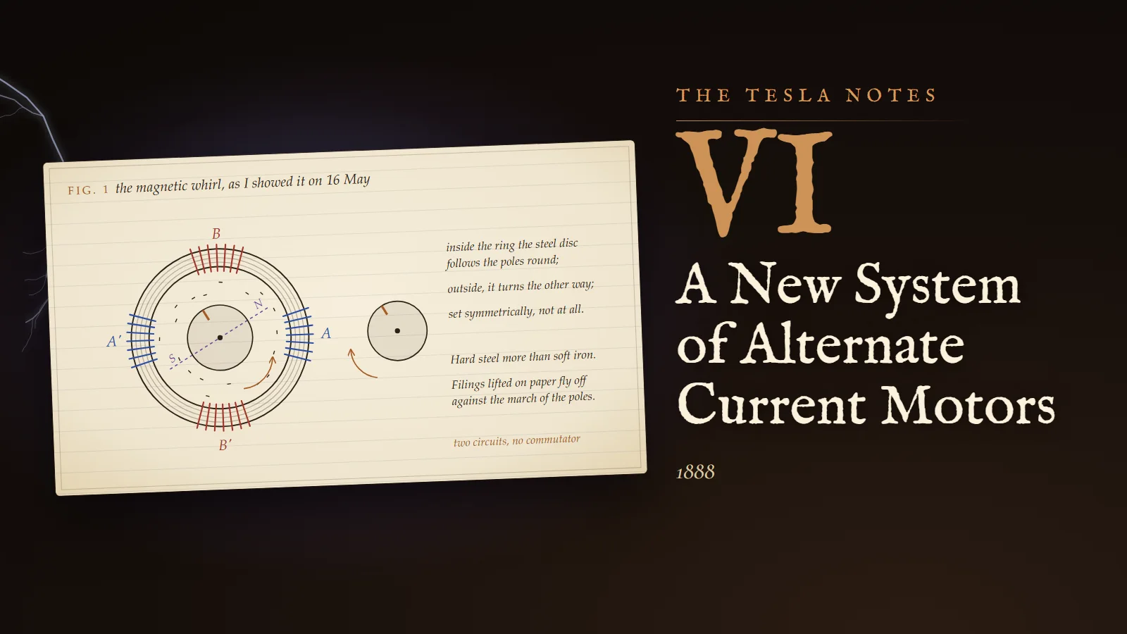
New York, 89 Liberty Street, the autumn of 1887. The printer downstairs has stopped his presses, his engine is turning my generator, and on the bench before me a ring of thin iron plates wound with four coils is making a small copper disc spin on a needle point with no wire touching it. Five years ago I drew this in the sand of the City Park in Budapest. Tonight it is iron and copper, and tomorrow it must become words, because a patent is a set of words and a lecture is a set of words, and without them the machine belongs to whoever describes it first. The question of this book is how to say, exactly enough for a patent examiner and an institute of engineers, what I have seen.
"In reality, therefore, all machines are alternate current machines, the currents appearing as continuous only in the external circuit during their transit from generator to motor."
Nikola Tesla, "A New System of Alternate Current Motors and Transformers", American Institute of Electrical Engineers, 16 May 1888
89 Liberty Street, 12 October 1887. The mother application
Filed today: an application for an electro-magnetic motor, the one from which all the others will be divided. Mr. Peck takes a half share, as we agreed. The attorneys wanted the claims broad, and I wanted them true, and we have arrived at both. The motor has two or more independent magnetising coils, each fed by its own circuit from a generator that has corresponding independent coils, so that the turning of the generator's armature causes, in the words of the specification, "a progressive shifting of the poles of the motor". I had to resist the temptation to write "a rotating field", because the examiner will look for the word in the old literature and find someone who used it carelessly.
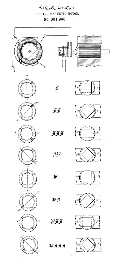
The generator is a drum armature with two coils at right angles, each brought out to its own pair of collecting rings. The motor is a ring of laminated iron with four coils, opposite coils joined to make one circuit, so that the ring has two circuits at right angles, A and B. Four wires, two circuits, no commutator anywhere. The armature of the motor is a disc or drum of iron with closed coils, or for the synchronous form, an armature excited separately.
Draftsman's note
For the drawing I have the whole sequence in eight positions, one for each eighth of a revolution of the generator. At the top the generator and the motor joined by their four wires. Down the left the ring, showing at each step where the resultant poles N and S stand: in position I at the top and bottom, in II shifted an eighth of the way round, in III a quarter, and so through VIII. Down the right the generator's armature in the same eight positions between its field poles. The draftsman at the attorneys' office drew it cleaner than I would have, and I let him.
Calculation
I owe the examiner, and myself, a proof that the shifting is uniform: that the resultant pole moves at constant speed and keeps constant strength. Let the two coils of the ring lie at right angles. Let coil A produce a magnetising effect along the horizontal proportional to its current c, and coil B along the vertical proportional to its current c₁, with the same constant K for both.
- Horizontal component: x = Kc. Vertical component: y = Kc₁.
- The generator's two coils are at right angles on one armature, so their currents are a quarter period apart. Let the armature have turned through the angle α. Then c₁ = K₁ sin α and c = K₁ sin(90° + α) = K₁ cos α.
- So x = KK₁ cos α and y = KK₁ sin α.
- The resultant has magnitude r with r² = x² + y² = (KK₁)²(cos²α + sin²α) = (KK₁)².
- Hence r = KK₁, a constant, and its direction makes the angle α with the horizontal: it turns exactly as the generator's armature turns.
The resultant is described by the equation of a circle. For a uniform field the two coils at right angles give the theoretical result, and the shifting poles keep a constant intensity. If the coils were not at right angles, or the currents not a quarter period apart, the tip of the resultant would trace an ellipse instead, and the pole would hurry and dawdle as it went round. I have measured it: with the ring as built, iron filings on a card show a pattern that does not favour any direction.
Reflection
When Mr. Peck and Mr. Brown first came to see the motors, Peck said, with a lawyer's courtesy, that he had heard of many perpetual motions. I could not make him see the rotating field with a diagram, so I put a copper egg on the ring, and it stood up on its end and spun. They asked no more questions. A man who will not follow an argument will often follow an egg.
89 Liberty Street, 30 November 1887. Two kinds of motor and the ratio of poles
Two more applications filed today. The first is the induction motor proper: independent field coils fed with alternating currents, and an armature wound with closed coils, short-circuited on themselves and connected to nothing. The second is a synchronous form, its armature fed by the alternating currents while the field magnet is excited by a separate source of continuous current.
These are two different animals, and I must be clear with myself about the difference before I am clear with anyone else.
Calculation
The synchronous motor first. Its field is a fixed magnet, excited by direct current, and it sits in the rotating field of the ring. Let the rotating field make the angle ωt with a fixed line and let the rotor's own poles make the angle β.
- Two magnets pull toward alignment with a torque proportional to the sine of the angle between them: T = k sin(ωt − β), with k fixed by the two strengths.
- Suppose the rotor is at rest, β constant. Average the torque over one period: (1/2π) ∫ sin(ωt − β) d(ωt) over 0 to 2π = 0.
- The field drags the rotor forward for half a period and backward for the other half. At rest the synchronous motor buzzes and does not start.
- Now suppose the rotor already turns at the speed of the field, β = ωt − δ with δ constant. Then T = k sin δ, steady.
- The load sets δ. More load, the rotor falls further behind, δ grows, and the torque grows to meet it, up to δ = 90°, where T = k. Beyond that the torque falls with further lag, the rotor drops out of step and stops.
So the synchronous motor has a small rotary effort at the start and a perfectly uniform speed at all loads up to its limit. That uniformity is its virtue; the specification of my first application says the problem "primarily, demands a uniformity of speed in the motor irrespective of its load". I wrote that in October and believed it. Now I believe it half.
The induction motor is the other animal. Its closed coils carry no current of their own; currents are induced in them only because the field slips past them. If the rotor turned with the field it would see no change of flux, no current would be induced, and there would be no torque. It must always lag, and the lag is what drives it. At standstill the slip is greatest, the induced currents largest, and the starting torque great: it pulls like a horse at the first step. Its speed falls a little with load, which is the price.
Calculation
Speed and the number of poles. The rotating field in a ring wound for two poles makes one turn for each period of the current. If the ring is wound for more poles, the field advances by one pair of poles in each period. Let the generator have n poles and the motor n₁. One revolution of the generator gives n/2 periods; the motor's field advances one pair of poles per period, which is 2/n₁ of a revolution. So the motor field turns (n/2)(2/n₁) = n/n₁ revolutions for each revolution of the generator.
speed of motor = speed of generator × n / n₁
In counting the motor's poles for this rule I take the magnets of one circuit. Suppose the generator has 12 poles and I want the motor to turn at 12/7 of the generator's speed: I build the ring with 14 magnets, seven in each of the two circuits, and give the armature 14 closed coils. Many ratios of whole numbers can be had this way, with no belts and no gears.
Margin
Reversal. Exchange the two wires of one circuit and the field turns the other way. The armature, running forward against a field that now runs backward, sees twice the slip, and the braking effort on it is enormous. A generator driven by power absorbs very nearly the third power of the speed when short-circuited on itself, so the reversed motor is stopped almost at once and started the other way. I tried it with a hand on the switch: the reversal is instantaneous. A belt would have come off.
89 Liberty Street, 10 April 1888. Three wires for four, and the arithmetic of copper
Filed today: a system of distribution with a single return wire common to the circuits. Mr. Brown, who spent his life with telegraph wires, asked the obvious question in February: if two circuits each have a wire going out and a wire coming back, why must there be two wires coming back? I had already thought of it, but his asking made me do the arithmetic properly.
Calculation
Two-phase, with a common return. Let the outgoing currents be, at the same strength I and a quarter period apart:
- i_A = I cos ωt and i_B = I cos(ωt − 90°) = I sin ωt.
- The return carries their sum back: i_R = I (cos ωt + sin ωt).
- Write cos ωt + sin ωt = √2 (cos 45° cos ωt + sin 45° sin ωt) = √2 cos(ωt − 45°).
- So the return carries a current of crest √2 I, an eighth of a period behind A.
The common wire is no idle wire. It carries 1.414 times what each outgoing wire carries and must be made thicker. Is it still a saving? Let me compare like with like.
I set the conditions: the same power P to be sent the same distance l, with the same total loss w in the line, and the same pressure V between each outgoing wire and its return. Let ρ be the resistivity of copper and let K = P²ρl²/(V²w).
- Single circuit, two wires. I = P/V, each wire of section a. Loss: 2I²ρl/a = w, so a = 2P²ρl/(V²w). Copper volume 2la = 4K.
- Two independent circuits, four wires, each circuit carrying P/2 with loss w/2. Each circuit needs copper 4(P/2)²ρl²/(V²(w/2)) = 2K; together 4K. No saving.
- Two circuits, three wires. Outgoing currents I = P/(2V); return √2 I. For least copper at a given loss, make the section of each wire proportional to its current: outgoing a, return √2 a. Loss: 2I²ρl/a + (√2 I)²ρl/(√2 a) = (2I²ρl/a)(1 + 1/√2) = w.
- Copper: l(2a + √2 a) = la(2 + √2). Substituting a: copper = 2(2 + √2)(1 + 1/√2) I²ρl²/w = 2(3 + 2√2) I²ρl²/w.
- With I² = P²/(4V²): copper = (3 + 2√2)/2 × K = 2.914 K.
Three wires need 2.914 / 4 = 72.9 per cent of the copper of four.
Calculation
And three circuits? My first application already shows, in Figures 13 and 14, a generator armature wound with three coils at sixty degrees apart, forming three independent circuits. Take the middle coil with its connections reversed: reversing a current is the same as shifting it half a period, 180°, so currents at 0°, 60° and 120° become currents at 0°, 240° and 120°, which is to say three currents each a third of a period behind the last. Join their three return wires into one. What does it carry?
- i_R = I [cos ωt + cos(ωt − 120°) + cos(ωt + 120°)].
- By the rule cos(a − b) + cos(a + b) = 2 cos a cos b, the last two terms are 2 cos ωt cos 120°.
- cos 120° = −½, so they sum to −cos ωt.
- i_R = I [cos ωt − cos ωt] = 0.
Three equal currents a third of a period apart sum to nothing at every instant. The common return carries no current at all; it may be cut away, and three wires serve three circuits. Geometrically: the three currents, drawn as lines of equal length at 120° to each other, close into an equilateral triangle, and the gap that would be the return current is zero.
The copper: with three wires and no return, each carrying I = P/(3V) with the same pressure V from each wire to the common point, the loss is 3I²ρl/a = w, so a = P²ρl/(3V²w), and copper 3la = K. That is a quarter of the single circuit. But this is unfair to the single circuit, because the pressure between two of the three wires is √3 V, and the insulation must stand the pressure between wires. Make the comparison at the same pressure V between any two wires instead. Then the pressure from each wire to the common point is V/√3, each current is P/(√3 V), the loss is 3I²ρl/a = P²ρl/(V²a) = w, so a = P²ρl/(V²w), and the copper is 3la = 3K, against 4K for the single circuit.
At equal pressure between wires, three-phase needs 75 per cent of the copper of a single circuit.
Draftsman's note
I have made the common wire visible as Plate VI. Choose two phases or three; the coloured wires carry the outgoing currents and the black one the return, its thickness proportional to what it carries. The small marks drift along each wire as the current flows and rock back as it reverses. On the right, the currents laid head to tail; below, their waves with the return current in heavy black. Unbalance the load on the last circuit and watch the return wake up.
Margin
For all that, I write in the specification that machines with three or more induced circuits joined at a common point are less efficient than my two-circuit arrangement, and I believe it for the machines I have built. The two-phase ring is simpler to wind, its field is perfectly circular with two coils, and I can show it to anyone with four wires. The arithmetic favours three; the workshop, today, favours two. I record both so that I do not later pretend I saw only one.
New York, 16 May 1888. Before the Institute
The lecture is given. I write this at two in the morning because I cannot sleep and because I want the order of things down before memory polishes it.
Professor William Anthony of Cornell arranged it, with the help of Mr. Pope and Mr. Martin, whom I thanked first. I had only days, and I said so at the beginning: "The notice was rather short, and I have not been able to treat the subject so extensively as I could have desired, my health not being in the best condition at present." Then I began with the commutator, which I called the source of most of the troubles in the operation of the machines, and showed that every dynamo generates alternating currents in its armature and turns them into continuous ones only to hand them to a motor that must turn them back again. Why rectify in order to un-rectify? The question I put was how to perform this operation by the direct action of alternate currents.
Then the ring. I described it as built, "made of thin insulated plates of sheet-iron and wound with four coils", and walked them through the positions of the poles, an eighth of a revolution at a time, until the poles had been shifted once round the periphery.
Experiment No. 1
The demonstrations, in the order I gave them.
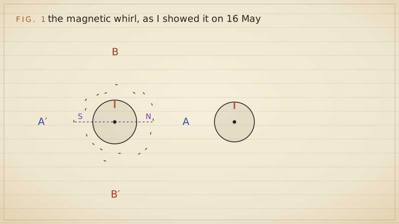
- A delicately pivoted disc of steel, held near the ring. Inside the ring it turned with the poles; held outside, it turned the other way; set symmetrically, it did not turn at all. A disc of hard steel is much more affected than a disc of soft iron, which I take to mean that the steel keeps a little magnetism from moment to moment and is dragged by the field as a magnet is dragged, besides the drag of its eddies.
- Iron filings on a sheet of paper over the ring. They vibrate in place; lifted a little, they are thrown away in a direction always opposite to the supposed movement of the poles. With the paper laid flat on the ring the existence of a magnetic whirl may be easily observed.
- For comparison I described the experiment in which a strongly energised electromagnet was rotated by mechanical power over the same disc: the phenomena are identical in every particular. That is the proof that my currents produce what a turning magnet produces.
- The synchronous motor coming into step: soft iron held near its field vibrates at first and then is weakly but permanently attracted; an incandescent lamp in its exciting circuit flickers until synchronism and then burns steady; a telephone receiver hums down through the octaves and falls silent.
Draftsman's note
Fig. 1 is the demonstration as the audience saw it: the ring with its two pairs of coils, the steel disc inside following the poles, a second disc outside turning against them, and the filings flung off. I have drawn the resultant pole as a dashed line that goes round.
Margin
Professor Anthony had tested two of my motors in the laboratory before the lecture, and I quoted his result with care: "At full loads the motors show efficiency fully equal to that of the continuous current motors." I gave the two types their characters plainly: one with a comparatively small rotary effort at the start but a perfectly uniform speed at all loads; the other with a great rotary effort at the start, the speed depending on the load. I let the engineers choose, and I saw some of them choose while I was still speaking.
Reflection
In the discussion Professor Elihu Thomson spoke of the alternating-current motor he has been building himself, which works by the repulsion of closed coils. I had named it among the existing motors at the start of my paper, honestly, with the others. He was courteous and so was I. I am certain his machine and mine stand on different principles: his reverses, mine rotates. But I noticed how carefully the room listened to him, a famous man, and how they looked at me afterward, a man with an accent and a borrowed suit. One lecture makes a beginning; a reputation takes years.
Walking home down the avenue at midnight I found I was reciting the Faust lines again, the ones I spoke in the park in 1882 when the field first turned in my head. Six years. The diagrams I drew in the sand were the diagrams on the Institute's screen tonight. I made no attempt to improve them. I reproduced the pictures as they appeared to my vision.
89 Liberty Street, 8 July 1888. Terms, and the other Mr. Brown
George Westinghouse's people have been here several times since the lecture, quiet men who ask good questions and look at the iron, not at me. Yesterday Brown and Peck agreed terms with them for my motor patents. I write the figures as I understand them: a sum in cash, a larger sum in notes, and a royalty of two and a half dollars for every horsepower of motor sold. I am to go to Pittsburgh to help the Westinghouse engineers make the motors on a large scale. My share of it is a third, by our company's agreement, and a third is reinvested. The man who dug trenches for two dollars a day eighteen months ago has signed a contract with the richest inventor in Pittsburgh. I keep looking at my hands.
Margin
A strange coincidence of names. On 5 June a Mr. Harold P. Brown, no relation of my Mr. Brown, published a letter in the New York Evening Post denouncing alternating current as deadly and demanding that its pressure be limited by law. He writes as an electrician; it is said he has friends in the direct-current companies. The New York legislature signed a law on 4 June to put condemned men to death by electricity from next January. I see where this is going. They will try to make the public afraid of the current my motor needs, by attaching it in their minds to the gallows.
Margin
Added in the autumn. I learn that Professor Galileo Ferraris of Turin read a paper to the Academy there in March, "Rotazioni elettrodinamiche prodotte per mezzo di correnti alternate", describing a rotating field made by two alternating currents differing in phase, with a copper cylinder dragged round by it. He built his apparatus in 1885, he says. I conceived mine in 1882, built it at Strasbourg in the summer of 1883 and filed in October 1887; he published first in print. I am told Westinghouse thought for a while of buying his rights instead of mine, and decided my patents would control the market. I respect Ferraris. He saw the field turn. But he concluded, I read, that such a motor could never be efficient, and he stopped. I did not stop.
Reflection
Tonight the laboratory is quiet. On the bench is the ring that turned the disc at the Institute, and beside it the copper egg, standing on its end in the dark because I left the current on to look at it. Next month I go to Pittsburgh, into a factory with a hundred engineers who have built alternating-current systems for two years and know things about practice that I do not. They will want my motor to run on their system. I am told their alternators make sixteen thousand alternations a minute. My motors were designed for much less. I suspect the next year will be spent arguing about one number.
Problems I set myself
1. Two coils at right angles carry currents c = K₁ cos α and c₁ = K₁ sin(α − ε), where ε is a small error in the phase difference. Show that the resultant field no longer has constant magnitude, and find its largest and smallest values for ε = 10°.
Answer. With x = KK₁ cos α and y = KK₁ sin(α − ε), r² = (KK₁)²[cos²α + sin²(α − ε)]. Using cos²α = ½(1 + cos 2α) and sin²(α − ε) = ½(1 − cos(2α − 2ε)), r² = (KK₁)²[1 + ½(cos 2α − cos(2α − 2ε))] = (KK₁)²[1 − sin ε sin(2α − ε)]. So r² swings between (KK₁)²(1 − sin ε) and (KK₁)²(1 + sin ε). For ε = 10°, sin ε = 0.1736: r runs from 0.909 KK₁ to 1.083 KK₁, an ellipse whose longer axis is about 19 per cent longer than its shorter.
2. A 16-pole generator turns at 450 revolutions a minute. What is the frequency of its currents, and how fast does the field of a 4-pole induction motor on its circuits turn?
Answer. Frequency f = (poles/2) × revolutions per second = 8 × 7.5 = 60 periods a second. Motor field speed = 450 × 16/4 = 1,800 revolutions a minute (equivalently 120f/p = 120 × 60/4). The rotor turns a few per cent slower, depending on the load.
3. A three-phase line has loads of 10, 10 and 7 amperes on its three wires, all at the same power factor. What current does a common return carry?
Answer. Write the third current as 10 amperes minus 3 amperes, both in its own phase. The three currents of 10 amperes a third of a period apart sum to zero, so the sum of the three line currents is a current of 3 amperes exactly opposite in phase to the third wire's, and that is what the return carries. In general the return carries the sum of the three currents drawn as lines at 120° to one another.
To the student who reads this later
You will call my "progressive shifting of the poles" a rotating magnetic field and write the result of my circle calculation in one line: with B_A = B cos ωt along x and B_B = B sin ωt along y, the vector B(t) = B(cos ωt, sin ωt) has constant length and turns at ω. With three coils 120° apart the same sum gives a field of 3/2 the strength of one coil's crest. In phasor notation, which Charles Steinmetz and Arthur Kennelly gave the profession in 1893, the zero sum of balanced three-phase currents is simply 1 + e^(−j2π/3) + e^(j2π/3) = 0, the three cube roots of unity adding to nothing.
My preference for two phases did not survive. Mikhail Dolivo-Dobrovolsky at AEG built three-phase machines in 1889, and in 1891 the Lauffen to Frankfurt line carried three-phase power 175 kilometres at 40 periods. The arithmetic I did on 10 April won: three wires, 75 per cent of the copper at equal voltage between conductors, and constant total power into a balanced load. Niagara's first generators in 1895 were two-phase, built on my patents; the world afterward went three-phase, still on my principle. My remark that three-circuit machines were "less efficient" was true of the machines I could build in 1888, and false as a prophecy.
About priority: Ferraris and I came to the rotating field independently. He built his apparatus in 1885 and published in March 1888; I held the American patents, filed in 1887, and American courts later upheld them. Walter Baily showed a disc turned by four electromagnets switched by hand in 1879, which is a rotating field made by a commutator. Historians today give Ferraris and me the field and give me the practical induction motor and the polyphase system. I can live with that.
To try today: a three-phase motor from a ceiling fan or a drill press, three resistive loads in star, and a clamp ammeter on the neutral. Balance the loads and watch the neutral current fall to nearly nothing; unbalance one and watch it return. Have a qualified person wire anything at mains voltage.
If you want to know what it was like to stand before the Institute in a borrowed suit, or why I trusted two phases over three, come and ask me.
Sources and liberties
The Tesla Notes are a modern reconstruction written in Nikola Tesla's voice by Eternal Gardens. Dates, patents, lectures, apparatus and quotations come from the sources below; the private reflections, the order of the working and the sketches are ours.
- Nikola Tesla, "A New System of Alternate Current Motors and Transformers", AIEE, 16 May 1888, reprinted in T. C. Martin, The Inventions, Researches and Writings of Nikola Tesla, Electrical Engineer, New York, 1894: Wikisource; Martin 1894 scan.
- US Patents 381,968 (Electro-Magnetic Motor, filed 12 October 1887), 382,279 (Electro-Magnetic Motor, filed 30 November 1887) and 381,969, all granted 1 May 1888: US381968, US382279, US381969.
- US Patent 390,413, System of Electrical Distribution, filed 10 April 1888, granted 2 October 1888: Google Patents.
- Nikola Tesla, "My Inventions", Electrical Experimenter, 1919, part IV: Wikisource.
- Nikola Tesla Museum, lecture list (16 May 1888): tesla-museum.org.
- W. Bernard Carlson, "Places of Invention: Nikola Tesla's Life in New York", Gotham Center, 2013: gothamcenter.org; and Carlson, Tesla: Inventor of the Electrical Age, Princeton University Press, 2013.
- Galileo Ferraris and the IEEE Milestone "Rotating Fields and Early Induction Motors, 1885 to 1888": Wikipedia; Ferraris's paper at ETHW.
- Harold P. Brown, letter of 5 June 1888 and the New York electrical execution law of 4 June 1888: Wikipedia.
- "Utility frequency" (Lauffen to Frankfurt, 1891, 40 Hz, 175 km): Wikipedia.
The Westinghouse terms of July 1888 differ between sources ($60,000 in cash and stock, or $25,000 cash and $50,000 in notes); all agree on $2.50 per horsepower, so the entry gives only that figure exactly. The 89 Liberty Street laboratory is dated 1886 by one Carlson article and April 1887 by Tesla. The copper egg shown to Peck and Brown is Tesla's own later account (Electrical Experimenter, March 1919). Thomson's remarks in the discussion and Tesla's private view of them, the walk home and the Ferraris margin's wording are our reconstruction; the claim that Ferraris doubted the efficiency of such motors is widely reported and should be read in his paper.