





Pittsburgh, August 1888. The air here tastes of coal and iron, the rivers run brown between the hills, and at night the furnaces along the Monongahela light the clouds from below as if the city were a forge with a sky for its hood. I have come to the Westinghouse works to make my motor a product. The engineers are able men and generous with their time, and within a day I understood that they and I disagree about one number. Their alternators give 16,000 alternations a minute, which is 133⅓ periods a second. My motor was conceived for far less. This book is the record of a year spent between two numbers, and of what each one costs in iron, in copper, in light and in turning.
"My system was based on the use of low frequency currents and the Westinghouse experts had adopted 133 cycles with the object of securing advantages in the transformation."
Nikola Tesla, "My Inventions", Electrical Experimenter, 1919
Pittsburgh, 21 August 1888. Sixteen thousand alternations a minute
A young engineer named Charles Scott, only lately come to the company, has been given to me as wireman and assistant for the tests. He is quick, careful, and writes everything down, which I like. The first afternoon we put one of my two-phase motors from Liberty Street on a pair of their alternators, coupled to give two currents a quarter period apart, and ran them up to their standard speed. The motor howled, ran far too fast for any machine it might drive, and its windings grew hot with currents that did no work.
Their reasons for the high frequency are good reasons. A belt-driven alternator with eight poles at 2,000 revolutions a minute gives 133⅓ periods; it is a compact, cheap machine. Their converters, as I showed in my notebook of last year, need less iron the higher the frequency. The whole of their lighting business, hundreds of central stations, is built on this standard, and they do not want to depart from their standard forms of apparatus. I am the newcomer asking them to change the foundation of the house so that my furniture will fit.
Calculation
The speed of the field. A ring wound for p poles has p/2 pairs. In each period of the current the field advances by one pair of poles, which is 2/p of a revolution. With f periods in a second, the field turns 2f/p revolutions in a second, or 120f/p in a minute:
n = 120 f / p revolutions per minute.
- At 133⅓ periods: 2 poles, 8,000 revolutions a minute; 4 poles, 4,000; 8 poles, 2,000.
- At 60 periods: 2 poles, 3,600; 4 poles, 1,800; 8 poles, 900.
- At 25 periods: 2 poles, 1,500; 4 poles, 750; 8 poles, 375.
A pump, a fan, a lathe, a hoist in a coal mine all want something between 600 and 1,800. At 133⅓ periods a motor that turns at 1,000 must have sixteen poles. I can wind sixteen poles on a ring. The question is what they cost.
Calculation
The cost of many poles. A motor's field lives mostly in the air gap between the stator and the rotor, because air is two thousand times less permeable than iron, and almost all the magnetising effort is spent driving lines across the gap. I want to know how the magnetising current depends on the frequency, for a motor of given size running at a given speed.
- The energy stored in a magnetic field per unit volume is B²/(2µ₀) in modern units. In the gap the field varies round the circumference, roughly as a sine; its average square is half the square of its crest. So the gap stores W = (Bₘ²/4µ₀) × (gap volume).
- The magnetising current flows in and out of the windings to set up and pull down this field, and the volt-amperes it costs, which do no work, are Q = ω W, where ω = 2πf. (For a coil of self-induction L carrying a current of crest Iₘ: Q = ωL (Iₘ/√2)² = ω × ½LIₘ², the angular frequency times the crest energy.)
- For the same rotor diameter, the same length, the same gap and the same crest density, W is the same whatever the number of poles. Only ω changes.
- The useful power at the same speed and torque is the same.
The magnetising volt-amperes per horsepower grow in proportion to the frequency.
Numbers for a motor of about five horsepower, the size the mines want: rotor 20 cm in diameter, 15 cm long, gap 1 mm, crest density 0.5 tesla.
- Gap volume = π × 0.20 × 0.15 × 0.001 = 9.42 × 10⁻⁵ cubic metre.
- W = 0.25 / (4 × 1.2566 × 10⁻⁶) × 9.42 × 10⁻⁵ = 4.69 joules.
- At 60 periods: Q = 377 × 4.69 = 1,770 volt-amperes, about half the motor's 3,700 watts of output.
- At 133⅓ periods: Q = 838 × 4.69 = 3,930 volt-amperes, more than the whole output.
The motor at 133⅓ periods must draw from the line more current for magnetising than for working. The generator must be built for it, the line must carry it, and the copper warms with it. Every extra pole I wind makes the pole pitch shorter for the same gap, so the gap grows in proportion to the pole and more of the lines leak from pole to pole without entering the rotor at all. The high frequency asks my motor to be a worse motor.
Reflection
Mr. Westinghouse came through the testing room in the evening, a big man with a walrus moustache and a handshake like a vice, and watched the motor run hot. He asked me only what I needed. I told him: a lower frequency. He laughed and said that was the one thing in Pittsburgh he could not give me this year. I respect him more than any man of business I have met. He listens with his whole face.
Pittsburgh, 4 October 1888. A motor for two wires
The difficulty doubles. Their system is single-phase as well as high in frequency, two wires from every station, and they will not string a third and fourth wire through every street for my sake. So I must make a motor capable of running efficiently at this frequency on two wires. The rotating field needs two currents differing in phase. On two wires there is only one current. I must make the second inside the motor.
Calculation
Splitting the phase. Wind the motor with two circuits at right angles, A and B, and connect both across the same two wires. If the two circuits had the same proportion of self-induction to resistance, their currents would be in step and the field would only pulsate. Give them different proportions.
- In a circuit of resistance R and self-induction L on a sine pressure, the current lags the pressure by the angle φ with tan φ = ωL/R. (I shall write out the proof properly in the notebook on the alternating wave; here I use the result.)
- Circuit A: many turns of thick wire on iron, ωL/R = 4. Lag φ_A = arctan 4 = 76.0°.
- Circuit B: fewer turns of fine wire, with a resistance in series, ωL/R = 0.5. Lag φ_B = arctan 0.5 = 26.6°.
- The two currents differ in phase by δ = 76.0° − 26.6° = 49.4°.
Now what field do two coils at right angles make when their currents differ by δ instead of 90°? I use the device of my Budapest notes: a pulsating field along one line is the sum of two half-strength fields turning opposite ways.
- Let each coil give a crest B. Coil A, along 0°, with current in phase 0: its field is a forward half B/2 at angle ωt and a backward half B/2 at angle −ωt.
- Coil B, along 90°, current lagging by δ: its forward half stands at angle 90° + ωt − δ and its backward half at 90° − ωt + δ.
- The two forward halves differ in angle by 90° − δ. Two equal lines of length B/2 at angle θ add to a line of length B cos(θ/2). So the forward field is B cos(45° − δ/2).
- The two backward halves differ by 90° + δ. The backward field is B cos(45° + δ/2).
- Check: δ = 90° gives forward B, backward 0, a pure rotating field; δ = 0 gives both 0.707 B, a pulsation along the diagonal.
- For δ = 49.4°: forward B cos 20.3° = 0.938 B; backward B cos 69.7° = 0.347 B.
The field is an ellipse: a strong field turning forward and a weaker one turning back. The rotor is pulled by both, and the torques, going nearly as the squares, are as 0.88 to 0.12. The motor starts and runs, the right way, with some seven parts of its effort out of eight pulling forward. It runs less sweetly than on two true phases, and the backward field heats the rotor, but it runs on two wires.
Experiment No. 1
Scott and I rewound a four-pole ring: circuit A of 2 × 140 turns of number 14 wire, circuit B of 2 × 90 turns of number 20 wire with a German-silver resistance in series, adjusted by trial. On their 133⅓-period circuit at full pressure the motor started unloaded in about four seconds and reached nearly its synchronous speed of 4,000 revolutions a minute. With a brake on the pulley it pulled down to perhaps 3,600 before it stalled. The resistance in circuit B grew hot enough to blister paint. I would not sell this motor. I would show it.
Margin
A condenser in series with circuit B would advance its current instead of merely lagging it less, and could bring δ to 90°. But a condenser large enough at this frequency would be a great box of tinfoil and paraffin paper, costly and apt to puncture. I note it for the future.
Margin
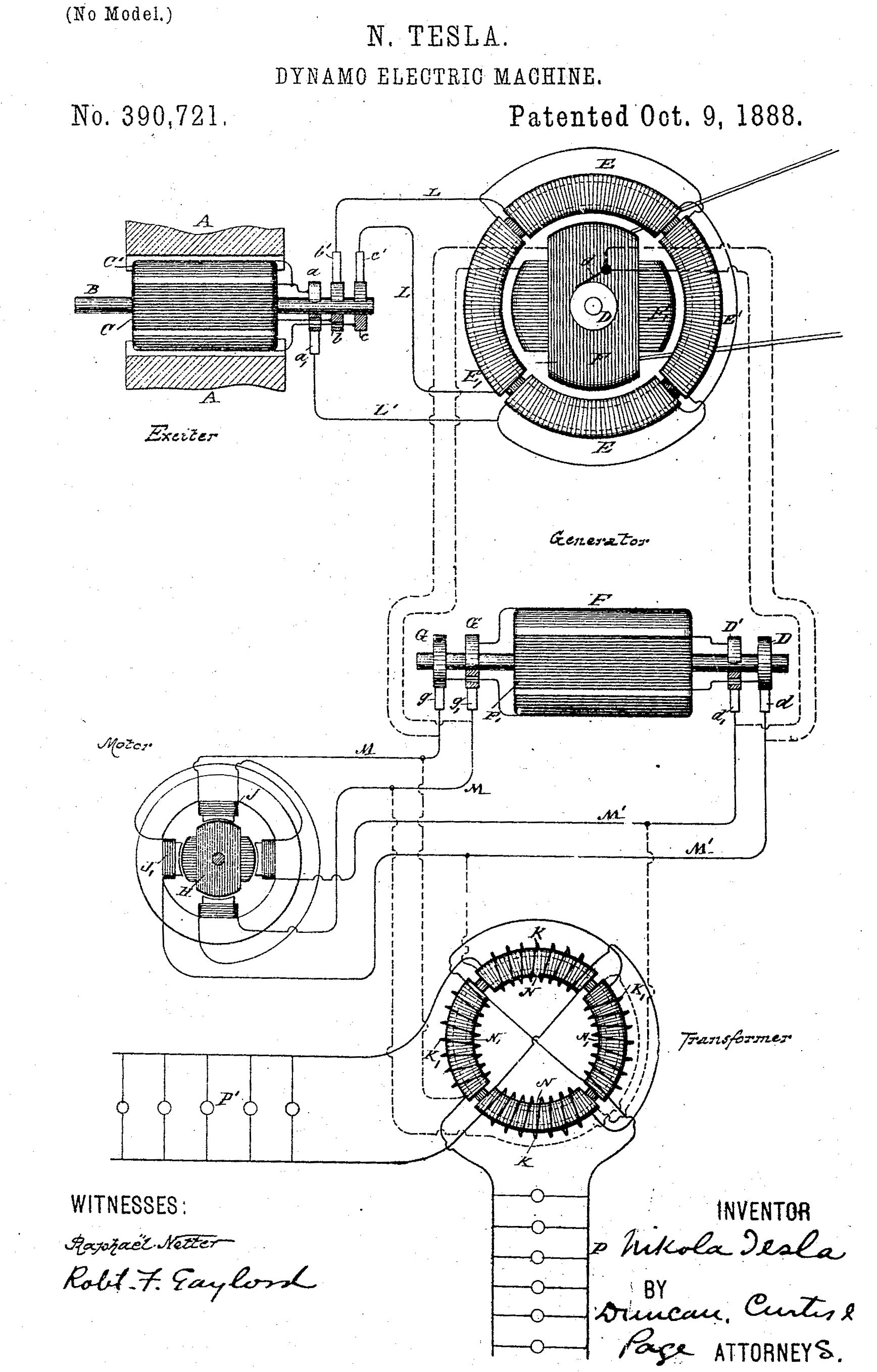
Added 9 October. A patent granted to me today shows the whole family on one sheet: an exciter, a generator whose own field is excited by alternating currents so that its poles shift and it can give its currents at a lower speed, a motor with four poles on two circuits, and one of my ring converters with its lamps. Looking at it here, among men who think in one phase and 133 periods, it seems a drawing from another country.
Pittsburgh, 6 December 1888. The lamp and the eye
The Westinghouse men have one argument against low frequency that I cannot dismiss with a calculation of motors: the lamps. On a slow alternation a lamp flickers. Arc lamps flicker worst, and their customers complain; incandescent lamps less, because the filament cannot cool much in the instant the current passes through zero. I promised Scott I would find how slow is too slow, by arithmetic before experiment.
Calculation
- The heat delivered to the filament is i²R. With i = I sin ωt: i²R = I²R sin² ωt = ½I²R (1 − cos 2ωt). The power pulsates at twice the frequency, from zero to twice its mean, every half period.
- The filament radiates. By Stefan's law of 1879 the radiation of a hot body goes as the fourth power of its absolute temperature: P = kT⁴. Near the working temperature T₀, a small rise ΔT increases the radiation by dP/dT × ΔT = (4P₀/T₀) ΔT.
- The filament has a heat capacity mc. Its temperature obeys mc dT/dt = (heat in) − (heat radiated).
- Write T = T₀ + θ with θ small. Then mc dθ/dt = −P₀ cos 2ωt − (4P₀/T₀) θ.
- Let τ = mcT₀/(4P₀), the time the filament takes to cool appreciably. The equation is τ dθ/dt + θ = −(T₀/4) cos 2ωt.
- Try θ = −A cos(2ωt − ψ). Substituting and comparing the sine and cosine parts: A = (T₀/4)/√(1 + (2ωτ)²), tan ψ = 2ωτ.
ΔT/T₀ = ¼ / √(1 + (2ωτ)²)
The heat capacity is a cushion, and the cushion is the more effective the higher the frequency and the thicker the filament.
Now τ for a lamp of sixteen candles. My estimate of the filament: carbon, 0.15 mm thick, 12 cm long, about 1.7 grams to the cubic centimetre, specific heat about 1,700 joules per kilogram per degree at these heats, working near 2,050 degrees absolute, taking about 50 watts.
- Mass = 1,700 × π × (1.5 × 10⁻⁴)²/4 × 0.12 = 3.6 × 10⁻⁶ kg, three and a half milligrams.
- mc = 3.6 × 10⁻⁶ × 1,700 = 6.1 × 10⁻³ joule per degree.
- τ = 6.1 × 10⁻³ × 2,050 / (4 × 50) = 0.063 second.
- At 60 periods, 2ωτ = 2 × 377 × 0.063 = 47.5, and ΔT/T₀ = 0.25/47.5 = 0.53 per cent: about ten degrees of swing on two thousand.
Ten degrees seems nothing. But the light is far more sensitive than the heat. On the photometer in the testing room I find that a rise of one per cent in pressure raises the candle-power by about six per cent; this is my own measurement, rough. The power goes as the square of the pressure and as the fourth power of the temperature, so the temperature goes as the square root of the pressure, and the candle-power as about the twelfth power of the temperature. A swing of 0.5 per cent in temperature becomes a swing of about 6 per cent in light.
- At 133⅓ periods: ΔT/T₀ = 0.23 per cent, light ± 2.7 per cent, rippling 267 times a second. Perfect steadiness to the eye.
- At 60 periods: light ± 6 per cent at 120 a second. Steady.
- At 25 periods: ΔT/T₀ = 1.2 per cent, light ± 15 per cent at 50 a second. Some eyes will see it, at the edge of the field of view.
- At 16⅔ periods: light ± 22 per cent at 33 a second. A plain flicker. Reading by it would tire anyone.
Draftsman's note
Plate VII gathers the three things the frequency governs. Top left, a motor of the chosen poles turning at its synchronous speed, slowed a hundredfold. Beside it, the cross-section a converter's core must have, compared with a 60-period core drawn dashed. The large panel is the light of a lamp over one twentieth of a second, with the filament thickness adjustable. Press the presets and watch the three verdicts change together.
Reflection
The newspapers bring news from New York that makes my calculation of lamps seem a parlour game. Yesterday, 5 December, Mr. Harold Brown killed calves and a horse with alternating current at 750 volts in Edison's laboratory at West Orange, before reporters, to show the State how to kill a man. In July he killed dogs at Columbia College, in the same building where I lectured in May. There is a word for using the death of animals to frighten people away from a rival's machine, and it is not science. Westinghouse says nothing in public and builds. I think he is right, and I am also furious. The current that will kill a man through a wet hand is the current that will turn ten thousand wheels and light a city. Fire is the same.
Pittsburgh, 18 February 1889. Iron against copper, and the frequency
I have been trying to state the whole question on one sheet, so that I can put it to the engineers as a sum instead of a quarrel.
Calculation
The converter. From my rule of 1887, V = 4.44 f N Φₘ. For a given pressure, turns and crest density, Φₘ = B × A, so:
- A = V / (4.44 f N B). The section of iron is inversely as the frequency.
- The length of the iron path is set mostly by the window that must hold the copper, roughly the same at any frequency. So the volume and weight of iron go as 1/f.
- Hysteresis: the loss per cycle per unit volume is the area of Ewing's loop, fixed by B. Loss per second is that area times f. Times the volume, which goes as 1/f: the total hysteresis loss is the same at any frequency.
- Eddies: per unit volume they go as f²t²B². Times the volume, as 1/f: the total eddy loss goes as f, unless the plates are made thinner in proportion.
So at 133⅓ periods a converter has 60/133⅓ = 0.45 of the iron of a 60-period converter, the same hysteresis loss, and somewhat more eddy loss. The Westinghouse men are right that the high frequency saves iron, and I concede it plainly. A central station may have hundreds of converters and one motor; iron at the converter is their chief cost.
Calculation
The motor and the lamp, from the entries above:
- Magnetising volt-amperes per horsepower, for the same speed: in proportion to f. At 133⅓, 2.2 times what they are at 60.
- Poles for 1,200 revolutions a minute: p = 120f/n. At 133⅓, 13.3, say 14; at 60, 6; at 30, 3, which is impossible, so 4 poles and 900 revolutions.
- Lamp flicker: acceptable down to about 40 periods; plainly visible below 25 for carbon lamps; earlier for arcs.
- Generator: f = pn/120. A belted machine at 900 revolutions with 8 poles gives 60 periods; for 133⅓ it must run at 2,000.
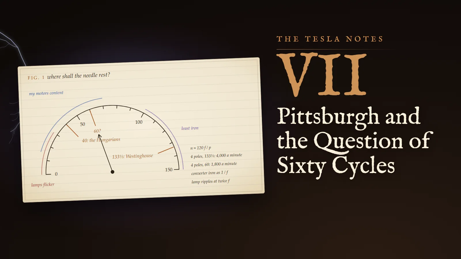
Laid together, the motor wants the frequency as low as the lamps allow, the lamps want it above forty, the converter wants it high. Where the curves cross, I find a band between about fifty and seventy. The Hungarians at Ganz run near forty. Somewhere between their forty and Westinghouse's 133⅓ there is a number that does all three tolerably and none of them perfectly. I write sixty, with a question mark, and leave it for the men who must build the stations.
Draftsman's note
Fig. 1, my dial: a half-circle marked from 0 to 150 periods, with an arc where the lamps flicker, an arc where my motors are content, and an arc where the converter iron is least. The Hungarians' 40 and Westinghouse's 133⅓ are marked in copper; sixty with a question mark. The needle swings between 133⅓ and 60 because that is the argument I have every day in this building.
Margin
Scott asked why I do not simply ask for two frequencies, one for lamps and one for motors. Because a system is worth what it costs to connect everything to everything. A city that runs two frequencies runs two cities.
Pittsburgh, 10 December 1889. My services no longer essential
The year is done and I am going back to New York. I write the phrase that I shall use when people ask me why: my services in Pittsburgh being no longer essential. It is true. The motors now run; the drawings are in the shops; there are men here, Scott and Shallenberger and the newer ones, who understand the rotating field as well as I do and will improve the details faster than I could, because details bore me once I have seen the principle.
Mr. Shallenberger told me the story of his meter. In the spring of last year a small spring fell into an arc lamp's coil in his laboratory, and he saw it turn, and he understood at once that two magnetic effects out of phase were turning it, exactly my field; he says he had not then seen my patents. By August he had patented an ampere-hour meter for alternating current that works on that principle. I felt no jealousy at all, only pleasure. When an idea is true it shows itself to several people at once, through whatever crack it can find.
Reflection
In the summer I went to Paris for the Exposition, saw Eiffel's tower standing over the Champ de Mars like a lesson in iron, and heard of the experiments of Professor Hertz, lately of Karlsruhe, with electric waves in space. I came back to Pittsburgh unable to think of anything else, and I suspect the engineers noticed. Low frequency for motors I have proved; the motors are theirs now. What I want to know is what happens at the other end of the scale: ten thousand alternations a second, a hundred thousand, a million. At such rates, I suspect, the converter needs no iron at all, the lamp needs no filament, and perhaps the line needs no wire.
On the train east tomorrow I will take only the notebooks. The question of sixty cycles I leave to Pittsburgh. I am going to look for the frequencies nobody has used.
Problems I set myself
1. A Westinghouse alternator has 8 poles. At what speed must it run to give 133⅓ periods, and at what speed to give 60? A 6-pole induction motor runs on each with 4 per cent slip; find its speed in both cases.
Answer. n = 120f/p: for 133⅓, n = 120 × 133.33/8 = 2,000 revolutions a minute; for 60, n = 900. The motor's field turns at 120 × 133.33/6 = 2,667 and 120 × 60/6 = 1,200; with 4 per cent slip the rotor turns at 2,560 and 1,152.
2. Two coils at right angles carry equal currents differing in phase by 60°. What are the strengths of the forward and backward rotating fields, as fractions of one coil's crest?
Answer. Forward B cos(45° − 30°) = B cos 15° = 0.966 B; backward B cos(45° + 30°) = B cos 75° = 0.259 B. The squares are 0.933 and 0.067, which sum to 1 as they must, since the forward and backward squares are (1 ± sin δ)/2.
3. A thicker filament of 0.30 mm, with τ twice as long, runs on 25 periods. Estimate the swing of its light.
Answer. τ ≈ 0.126 s, so 2ωτ = 2 × 157.1 × 0.126 = 39.6, and ΔT/T₀ = 0.25/39.6 = 0.63 per cent. With light going as the twelfth power, the swing is about 12 × 0.63 ≈ ± 7.6 per cent. A thicker filament buys steadiness at low frequency, but it needs more current for the same light, so lamps for low frequencies are made for lower pressures.
To the student who reads this later
Westinghouse settled on 60 periods in 1890, after I had left. The reason given in the company's own later account (Benjamin Lamme, "The Technical Story of the Frequencies", 1918) was that existing arc-lighting apparatus worked a little better at 60 than at 50, and that 60 suited both lamps and induction motors. Whether my arguments in that building moved the needle I cannot prove to you; I have only the notebook. AEG in Germany raised its standard to 50 in 1891 after seeing lamps flicker on the 40-period Lauffen to Frankfurt line. Niagara in 1895 used 25, because its turbines had already been specified at 250 revolutions a minute and 12 poles at 250 gives 25. Your world is divided to this day between 50 and 60, and your railways and aircraft use other numbers again, 16.7 and 400. Every one of those choices is the same compromise I set out on 18 February 1889: iron against copper against light against speed.
In your notation the split-phase calculation is a sum of phasors: a field B_x = B cos ωt, B_y = B cos(ωt − δ) decomposes into forward and backward circularly polarised components of magnitudes B cos(45° ∓ δ/2). The capacitor-start and permanent-split-capacitor motors in your refrigerators and fans are my "Margin" of 4 October made cheap by the electrolytic and film condensers I did not have. The magnetising argument is your power factor: an induction motor's magnetising reactive power at fixed speed and size scales with frequency, which is one reason 400-period aircraft motors are small and high-speed.
The lamp calculation is a first-order thermal low-pass filter, and my rule that light goes as the twelfth power of temperature is a rough form of what Planck's law of 1900 gives at these temperatures: near 555 nanometres and 2,050 kelvin, d ln B/d ln T ≈ hc/(λkT) ≈ 12.6. Modern measurements of tungsten lamps at 60 hertz show a few per cent flicker, the same order as my estimate for carbon. Your LED lamps have almost no thermal cushion at all, and their makers must smooth the current electronically or you see the flicker I feared at 16⅔.
To try today: film an incandescent bulb and an inexpensive LED bulb with a phone camera's slow-motion mode at 240 frames a second, and count the ripples. The bulb's ripple is at twice your mains frequency, and its depth is small; some LEDs ripple fully.
If you want to argue about sixty against fifty, or hear what Westinghouse said in the testing room, come and ask me.
Sources and liberties
The Tesla Notes are a modern reconstruction written in Nikola Tesla's voice by Eternal Gardens. Dates, patents, lectures, apparatus and quotations come from the sources below; the private reflections, the order of the working and the sketches are ours.
- Nikola Tesla, "My Inventions", Electrical Experimenter, 1919, part IV (133 cycles, the two-wire motor, "my services in Pittsburg being no longer essential"): Wikisource.
- Charles F. Scott, "The Contribution of Tesla to Electrical Power Development", Zagreb, 1929, and his greeting of 1931, on joining Westinghouse in August 1888 as Tesla's wireman and assistant: croatianhistory.net.
- "Utility frequency" (8-pole machines at 2,000 rpm giving 133 Hz; the 1890 choice of 60 Hz; AEG's 50 Hz in 1891; Niagara's 25 Hz; transformer size inversely proportional to frequency): Wikipedia; B. G. Lamme, "The Technical Story of the Frequencies", Transactions of the AIEE, 1918.
- US Patent 390,721, Dynamo-Electric Machine, granted 9 October 1888: Google Patents.
- Harold P. Brown, the Columbia demonstration of 30 July 1888 and the West Orange demonstration of 5 December 1888: Wikipedia.
- Oliver B. Shallenberger's alternating-current meter, patented 14 August 1888, and the fallen spring: ETHW, Electric Meter.
- Paris Exposition of 1889 and Tesla's first news of Hertz: W. Bernard Carlson, Tesla: Inventor of the Electrical Age, Princeton University Press, 2013; Tesla, "The True Wireless", 1919: Wikisource.
- W. Bernard Carlson, "Places of Invention: Nikola Tesla's Life in New York", Gotham Center, 2013: gothamcenter.org.
No primary source shows that Tesla personally championed 60 cycles; "My Inventions" says only that his system was based on low frequencies, and the entry keeps his sixty as a private estimate. The Westinghouse visit to the testing room, his words, the split-phase winding and its test figures, the photometer measurement and the Shallenberger conversation are our reconstruction; the filament model uses textbook values for carbon and is meant as an order-of-magnitude estimate.