





Pittsburgh, January 1889, and later New York. Every engineer in this building can wind a coil, and hardly one of them can tell me in advance what current it will take on a sine pressure of 133 periods. They measure and they guess. I want a method that lets me see the alternating current as I see a machine, whole and running, before a single turn is wound, and I want it simple enough to do on the back of an envelope in a railway carriage. This notebook is the collection of that method, entry by entry, from the turning radius to the resonance of a coil with a condenser. It is the part of my work I am proudest of and talk about least, because mathematics done well looks obvious afterward.
"Up to a certain degree of complexity it was absolutely the same to me whether I wrote the symbols on the board or conjured them before my mental vision."
Nikola Tesla, "My Inventions", Electrical Experimenter, 1919
Pittsburgh, 13 January 1889. The radius that turns
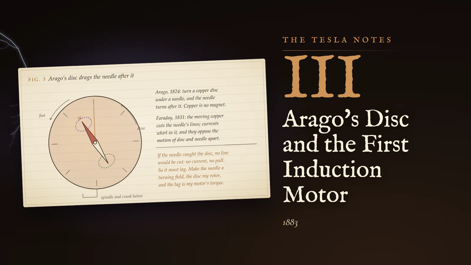
At Graz, in Professor Pöschl's optics, I learned Fresnel's way of adding two vibrations of the same period: draw each as a line whose length is its amplitude and whose angle is its phase, add the lines as forces are added, and read the amplitude and phase of the sum from the resultant. Fresnel did it for light. It works for anything that goes as a sine, and an alternating current is the most perfect sine I know, since my generator's coil turning at constant speed makes it.
So here is the picture I shall use for everything. A radius of length A turns about a centre at the steady rate of ω radians a second, counterclockwise. Its shadow on the vertical line, its height above the centre, is A sin(ωt + α), where α is the angle it had at the start. Every sine wave of the frequency f = ω/2π is the shadow of such a turning radius. Since all the radii of one circuit turn together at the same ω, I may stop the turning in my mind, as one stops a wheel with a flash of light, and work with the radii standing still. Their lengths are the amplitudes, their angles the phases, and their relations to one another never change.
Calculation
Prove that the sum of two waves of the same period is a wave of the same period, and find it.
- Let x₁ = a sin ωt and x₂ = b sin(ωt + φ).
- Expand the second: b sin ωt cos φ + b cos ωt sin φ.
- Sum: x₁ + x₂ = (a + b cos φ) sin ωt + (b sin φ) cos ωt.
- Any expression P sin ωt + Q cos ωt equals R sin(ωt + ψ) with R cos ψ = P and R sin ψ = Q, as one sees by expanding sin(ωt + ψ).
- So R² = P² + Q² = (a + b cos φ)² + (b sin φ)² = a² + 2ab cos φ + b²(cos²φ + sin²φ).
R² = a² + b² + 2ab cos φ, tan ψ = b sin φ / (a + b cos φ)
This is the rule of the triangle: R is the third side of a triangle whose two sides are a and b with the angle 180° − φ between them. Exactly the construction of Fresnel. Two equal waves in step (φ = 0) give twice the amplitude; in opposition (φ = 180°) they give nothing; a quarter period apart (φ = 90°) they give √2 times one of them, which is the current of my common return wire of last April, appearing again by a different road.
Margin
And a quarter period of lead is a turning of the radius through 90°. When I differentiate a sine, A sin ωt becomes ωA cos ωt = ωA sin(ωt + 90°): the derivative is the same radius, lengthened ω times and turned forward a quarter. When I integrate, the radius is shortened ω times and turned back a quarter. This is the key to the whole subject. A coil, whose pressure goes as the rate of change of its current, turns its radius forward; a condenser, whose charge is the integral of its current, turns it back.
Pittsburgh, 2 March 1889. The effective value, by integration
For two years I have used the rule that a sine current reads on a hot-wire instrument as its crest divided by √2, and I have used it on faith. Tonight I prove it, because a man who builds on faith in arithmetic deserves the bridge that falls.
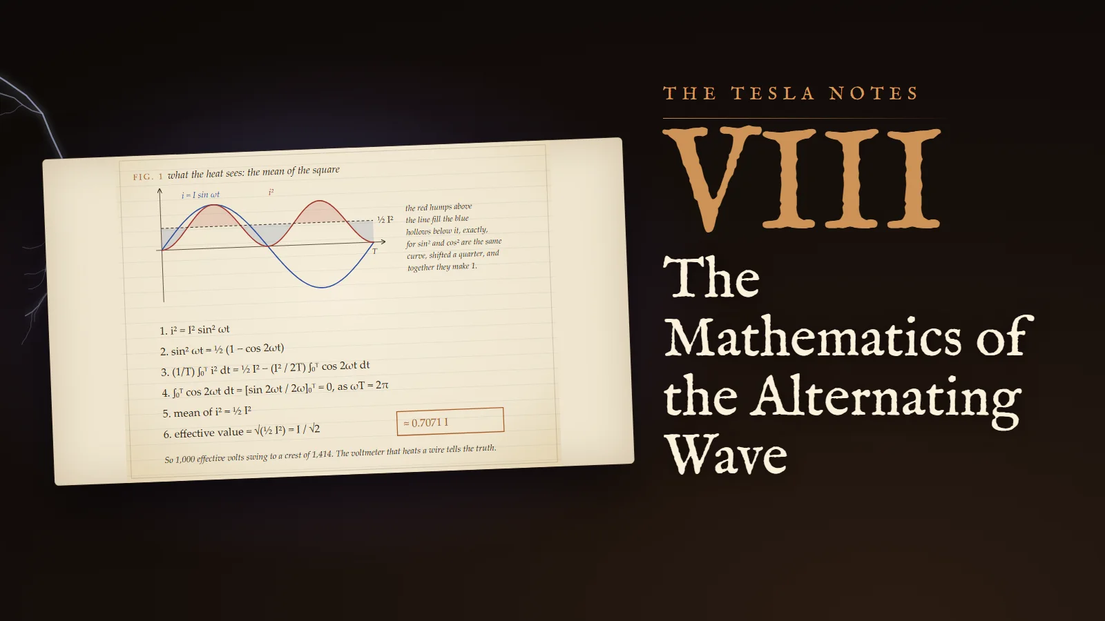
What does "effective" mean? A current is effective in heating a resistance R at the rate i²R. A steady current I_s heats at I_s²R. An alternating current heats at a rate that changes from instant to instant, and its average rate over a period is the average of i²R. The effective value of the alternating current is the steady current that would give the same average heat: I_s² R = mean of (i²R), so I_s = √(mean of i²). The root of the mean of the square. The direction of the current does not enter, because the square forgets the sign: heat cannot tell forward from backward.
Calculation
Let i = I sin ωt, with I the crest, and T = 2π/ω the period.
- i² = I² sin² ωt.
- From cos 2θ = 1 − 2 sin²θ: sin² ωt = ½(1 − cos 2ωt).
- Mean of i² over a period = (1/T) ∫₀ᵀ I² sin² ωt dt = (I²/2T) ∫₀ᵀ (1 − cos 2ωt) dt.
- The first part: (I²/2T) × T = ½I².
- The second part: ∫₀ᵀ cos 2ωt dt = [sin 2ωt / 2ω] from 0 to T = (sin 4π − sin 0)/2ω = 0, since ωT = 2π.
- So the mean of i² is exactly ½I².
effective current = I / √2 = 0.7071 I
There is a second proof, which I like better because I can do it with my eyes shut. Over a whole period sin²ωt and cos²ωt have the same average, since one is the other shifted by a quarter period and a whole period has no preferred beginning. Their sum is 1 at every instant. So each averages ½. No integral is needed, only symmetry.
Draftsman's note
I have drawn the working as Fig. 1, the page as it stands in this book. At the top, one period of i in blue and of i² in red. The red curve never goes below zero, it has twice the frequency, and it oscillates exactly about the dashed line at ½I². The humps above the line are the same shape as the hollows below it, and fill them: the line at ½I² is the level the red water would settle to if the curve were a vessel. Below, the six steps.
Calculation
For comparison, the plain average of the current, taken without regard to sign, which is what a commutated dynamo delivers and what my old Graz machine's brushes made of its alternating current.
- Over the first half period the current is positive. Its mean there is (2/T) ∫ I sin ωt dt, taken from 0 to T/2, which equals (2/T)(I/ω)[−cos ωt] from 0 to T/2.
- [−cos ωt] from 0 to π/ω = −cos π + cos 0 = 2.
- So the mean is (2/T)(2I/ω) = 4I/(ωT) = 4I/2π = 2I/π = 0.6366 I.
The effective value exceeds the mean value in the ratio 0.7071/0.6366 = 1.1107. An instrument that reads the mean, if one rectified the current for it, would read eleven per cent low for heat. The ratio is a property of the shape of the wave; a peaked wave has a larger ratio, a flat-topped one a smaller. The sine has its own.
Experiment No. 1
Three instruments in series on one alternating circuit of a few amperes, from a small Westinghouse alternator: a Siemens electrodynamometer, in which the current in a fixed coil acts on the same current in a movable coil, so that the deflection goes as i² at every instant and the needle, too heavy to follow, settles at the mean of i²; a Cardew hot-wire voltmeter across a known resistance, which reads by the expansion of a wire heated by i²; and a d'Arsonval galvanometer with a permanent magnet, whose deflection goes as i itself. Result: the electrodynamometer and the Cardew agreed within two per cent. The galvanometer's needle trembled about zero and read nothing, because the mean of i is zero over a period. The current that lights a lamp and turns a motor is, to a permanent magnet, nothing at all.
Reflection
The crest is what the insulation must stand. A circuit of 1,000 effective volts swings to 1,414 volts and back to minus 1,414 every period, and the cotton and shellac must hold the crest, not the reading. The Edison men who call our current deadly at a thousand volts may as well say 1,414. I shall not be the one to point it out to them.
Pittsburgh, 20 May 1889. The spurious resistance of a coil
Ohm's law, V = IR, tells me the current a steady pressure drives through a resistance. A coil on alternating current takes far less current than its resistance allows, because its own changing flux sets up a pressure against the current. Some of the English writers have called this the spurious resistance of the coil. Mr. Heaviside, who has a talent for words to match his talent for equations, calls the whole opposition of a circuit to an alternating current its impedance. I take his word. Now I want its value.
Calculation
- A coil of resistance R and self-induction L carries the current i = I sin ωt.
- The pressure needed to drive it is the sum of two parts: Ri to overcome the resistance, and L di/dt to overcome the self-induction.
- v = RI sin ωt + ωLI cos ωt.
- In the picture of turning radii: the first part is a radius of length RI along the current's radius; the second, of length ωLI, stands a quarter period ahead of it.
- They are at right angles, so the applied pressure is the hypotenuse: V = I √(R² + ω²L²).
- Its angle ahead of the current: tan φ = ωL/R.
Z = √(R² + ω²L²), φ = arctan(ωL/R)
The impedance Z is the hypotenuse of a right triangle whose sides are the resistance R and the quantity ωL, which has the dimensions of a resistance and is measured in ohms. The current is V/Z and lags the pressure by the angle φ at the corner of the triangle. Increase the frequency and ωL grows, the triangle stands up, the current shrinks and swings further behind.
Worked: one circuit of my two-phase motor, R = 2 ohms, L = 0.02 henry.
- At 133⅓ periods: ω = 837.8; ωL = 16.76 ohms; Z = √(4 + 280.8) = 16.87 ohms; φ = arctan 8.38 = 83.2°.
- At 60 periods: ω = 377.0; ωL = 7.54 ohms; Z = √(4 + 56.8) = 7.80 ohms; φ = arctan 3.77 = 75.1°.
On the same 100 effective volts, the coil takes 5.93 amperes at 133⅓ and 12.8 amperes at 60. At 133⅓ periods my winding chokes itself and the motor is starved; at 60 it breathes. This is the arithmetic beneath my quarrel with the Westinghouse frequency, and it is why I must wind fewer turns for the high frequency and then fight the leakage.
Margin
Measuring L. Pass a known alternating current through the coil, read the effective pressure across it with the Cardew and the resistance with a Wheatstone bridge on direct current. Then Z = V/I, and ωL = √(Z² − R²). It is the cleanest measurement of self-induction I know, and it needs no ballistic galvanometer.
New York, 8 October 1890. Watts that are not watts
I am back in New York, in a laboratory on Grand Street of my own, with the Westinghouse money to pay for it. Before I go wholly into my high-frequency work I must close an account with the low frequencies that has troubled me since Pittsburgh. The Westinghouse men noticed that a motor's voltmeter reading times its ammeter reading is always more than the power measured by a wattmeter or by the brake on its pulley. They call the product the apparent watts. The difference is real current flowing in the line and doing no work, and it costs copper and coal.
Calculation
- Let the pressure be v = V sin ωt and the current lag by φ: i = I sin(ωt − φ), with V and I the crests.
- The power at each instant is p = vi = VI sin ωt sin(ωt − φ).
- By the identity sin A sin B = ½[cos(A − B) − cos(A + B)]: p = ½VI [cos φ − cos(2ωt − φ)].
- The second term oscillates at twice the frequency and averages to zero over a period.
- Mean power: ½VI cos φ.
- With effective values V/√2 and I/√2: mean power = (V/√2)(I/√2) cos φ.
true watts = effective volts × effective amperes × cos φ
The cosine of the lag is the fraction of the apparent watts that does work. In the turning-radius picture, split the current's radius into two parts: I cos φ along the pressure, which carries the power, and I sin φ at right angles to it, which carries none and only sloshes energy into the coil's field and back each quarter period. The second is the wattless current. The instantaneous power curve goes negative for a part of each half period, by the amount of the lag: the motor returns energy to the line for those instants.
Worked: a motor on a 1,000-volt circuit takes 10 amperes with a lag of 53.1°, so cos φ = 0.6.
- Apparent watts: 1,000 × 10 = 10,000.
- True watts: 10,000 × 0.6 = 6,000.
- Working current I cos φ = 6 amperes; wattless current I sin φ = 8 amperes.
- The line heats as the square of the whole 10 amperes. If only the 6 working amperes flowed, the loss would be 36/100 of what it is. Nearly two thirds of the line loss is paid for current that does no work.
Calculation
The cure. A condenser takes a current that leads the pressure by a quarter period, because its charge q = Cv follows the pressure and its current is i = dq/dt = C dv/dt: with v = V sin ωt, i = ωCV cos ωt = ωCV sin(ωt + 90°). Its impedance is 1/(ωC), and its current radius stands a quarter ahead of the pressure, opposite to the coil's wattless current. Put a condenser across the motor and choose it to take exactly the 8 wattless amperes:
- ωCV = 8, with V = 1,000 effective volts and ω = 837.8 at 133⅓ periods.
- C = 8 / (837.8 × 1,000) = 9.55 × 10⁻⁶ farad, 9.55 microfarads.
- The line then carries only the 6 working amperes, in step with the pressure, and the wattless 8 amperes slosh between motor and condenser without troubling the line at all.
Nine and a half microfarads to stand a thousand volts is a large condenser for 1890, a cabinet of tinfoil and paraffined paper. I note it, and leave it for the manufacturers.
Draftsman's note
Plate VIII is the method entire. On the left, the turning radii: the applied pressure in black, the current in blue, and the three pressures across the parts of the circuit, IR in green along the current, IωL in red a quarter ahead, I/ωC in violet a quarter behind; the last two oppose and the dashed line shows what remains of them. Their shadows are drawn to the right as waves, with the power vi in faint copper. Set R, L, C and the frequency and read the impedance, the lag, the cos φ and the true watts. Then hunt for the frequency at which the current comes into step with the pressure.
Grand Street, 3 February 1891. A coil and a condenser in one circuit
The last entry of this book and the first of the next. In my oscillation work this winter a condenser discharges into a coil and the two pass energy back and forth like a pendulum, and I have found that the whole behaviour is already inside the simple series circuit of a coil, a condenser and a resistance on a sine pressure. Lord Kelvin found the free oscillation of such a circuit in his paper on transient currents, which I believe was in 1856; Maxwell worked out its response to an alternating pressure. Here it is in my own way.
Calculation
- Series circuit: R, L and C, current i = I sin ωt.
- Pressures: across R, RI sin ωt, along the current; across L, ωLI, a quarter ahead; across C, I/(ωC), a quarter behind.
- The coil's and the condenser's radii lie on one line in opposite directions; they subtract. The net is (ωL − 1/(ωC)) I, at right angles to the current.
- So V = I √(R² + (ωL − 1/(ωC))²) and tan φ = (ωL − 1/(ωC))/R.
Z = √(R² + (ωL − 1/ωC)²)
At low frequency 1/(ωC) is large, the condenser wins, and the current leads. At high frequency ωL is large, the coil wins, and the current lags. Between them is one frequency where they are equal:
- ω₀L = 1/(ω₀C), so ω₀² = 1/(LC).
- ω₀ = 1/√(LC), f₀ = 1/(2π√(LC)).
- There Z = R exactly. The coil and condenser vanish from the circuit as far as the source can tell, and the current is V/R, in step with the pressure.
- But the pressure across the coil alone is ω₀L × V/R. Call Q = ω₀L/R. The coil sees Q times the applied pressure, and so does the condenser, in opposite phase.
Worked: L = 0.1 henry, C = 2 microfarads, R = 5 ohms, 100 effective volts applied.
- LC = 0.1 × 2 × 10⁻⁶ = 2 × 10⁻⁷; √(LC) = 4.472 × 10⁻⁴ second.
- ω₀ = 2,236 radians a second; f₀ = 2,236/2π = 355.9 periods a second.
- Current at resonance: 100/5 = 20 amperes.
- ω₀L = 223.6 ohms, so Q = 223.6/5 = 44.7.
- Pressure across the coil: 44.7 × 100 = 4,470 effective volts, 6,320 at the crest.
A hundred volts in, four and a half thousand across the coil. Nothing is created: the energy stored swings between the coil's field, ½LI², and the condenser's charge, ½CV², twice each period, and the source supplies only what the resistance burns. The magnification is the patience of the circuit. Each cycle the source adds a little, as a child's push adds to a swing, and the swing builds until its losses equal the pushes.
Experiment No. 2
To check the arithmetic at a frequency I can make: a coil of 0.1 henry and 5 ohms on my 133⅓-period alternator would need C = 1/(ω²L) = 1/(837.8² × 0.1) = 14.2 microfarads. I had 12 microfarads of paper condensers and made up the rest with a small adjustable Leyden battery. At 50 volts applied the hot-wire voltmeter across the coil read some 700 volts before I took my hand off the switch, for the condensers were complaining. With R = 5 the ideal is 50 × 837.8 × 0.1/5 = 838 volts; my coil's iron and the condensers' losses make up the difference.
Reflection
This is the door to the next book. If L and C are small, f₀ is enormous; a coil of a few turns and a Leyden jar resonate at hundreds of thousands of periods, and Q, with care, can be large. Then a modest pressure applied in tune builds a great one. I have seen it in the spark of the induction coil this winter and I mean to make an instrument of it. Kelvin's formula is the whole secret, and resonance is the lever. I sit here with Ohm's law grown into a triangle and the triangle grown into a pendulum, and I think that the alternating current is the most natural thing in the world: the earth turns, the tides breathe, the heart beats, and the current goes back and forth in obedience to the same mathematics.
Problems I set myself
1. A sine current of crest I passes through a single rectifying contact that lets only the positive half-waves through. Find its effective value and its mean value.
Answer. The square is I² sin²ωt for half the period and zero for the other half, so its mean is half of ½I², that is ¼I², and the effective value is I/2. The mean value is half of 2I/π, that is I/π = 0.318 I. The ratio of effective to mean is (I/2)/(I/π) = π/2 = 1.571, larger than the 1.111 of the full sine because the wave is more peaked in time.
2. A coil of R = 3 ohms and L = 0.05 henry is put on 110 effective volts at 60 periods. Find ωL, Z, the current, the lag and the true watts.
Answer. ω = 377.0, ωL = 18.85 ohms. Z = √(9 + 355.3) = 19.09 ohms. Current = 110/19.09 = 5.76 amperes, lagging by arctan(18.85/3) = 81.0°. True watts = I²R = 5.76² × 3 = 99.6, which agrees with V I cos φ = 110 × 5.76 × 0.157 = 99.6. The apparent watts are 634: the coil takes six times as much current as its work requires.
3. Choose the condenser to resonate with a coil of L = 0.2 henry and R = 4 ohms at 133⅓ periods. With 50 effective volts applied, find the current and the pressure across the coil.
Answer. C = 1/(ω²L) = 1/(837.8² × 0.2) = 7.12 microfarads. At resonance the current is 50/4 = 12.5 amperes, in step with the pressure. ωL = 167.6 ohms, so Q = 41.9 and the coil sees 12.5 × 167.6 = 2,094 effective volts, nearly forty-two times the supply.
To the student who reads this later
My turning radii are your phasors. In 1893 Arthur Kennelly showed that impedance behaves as a complex number, and Charles Steinmetz, the same year, taught the profession to write every sine quantity as a complex number with j = √(−1) as the operator that turns a radius forward by 90°. In your notation v(t) = Re{√2 V e^(jωt)}, the coil's impedance is jωL, the condenser's 1/(jωC) = −j/(ωC), and my whole fifth entry is one line: Z = R + j(ωL − 1/(ωC)), I = V/Z. The word reactance for ωL and 1/(ωC) was proposed by Édouard Hospitalier in May 1893, after these entries; I have kept it out of the dated pages for that reason. "Effective value" you call RMS, "apparent watts" your volt-amperes S = VI, "true watts" your real power P = VI cos φ, my wattless current your reactive power Q = VI sin φ, and the triangle of P, Q and S your power triangle. Power-factor correction with capacitors, my 9.55 microfarads, is done in every factory you will ever visit.
Where I was incomplete: everything here assumes a pure sine. Real alternators, and especially the iron of converters, distort the wave, and the effective value of a distorted wave is the root of the sum of the squares of its harmonics, by Fourier's theorem. Your "true RMS" meters exist because instruments calibrated on my 0.7071 read wrongly on distorted waves. Kelvin's paper on transient currents, which I gave as 1856 from memory, appeared in 1853.
To try today: a 100 mH inductor, a 2 µF film capacitor rated for the voltage, a 10 Ω resistor and a signal generator at 5 volts. Sweep the frequency through about 356 Hz and measure the voltage across the inductor; with real resistances your Q will be lower than mine, and the peak will still astonish you. Keep the drive low: resonant circuits make high voltages from small ones, which is exactly the point.
If you want to hear how I see a sine wave as a turning radius, or why the mean of the square is the only honest average for heat, come and ask me.
Sources and liberties
The Tesla Notes are a modern reconstruction written in Nikola Tesla's voice by Eternal Gardens. Dates, patents, lectures, apparatus and quotations come from the sources below; the private reflections, the order of the working and the sketches are ours.
- Nikola Tesla, "My Inventions", Electrical Experimenter, 1919, part III (visualising mathematics) and part IV (Grand Street, Kelvin's discharge given as 1856): Wikisource.
- Nikola Tesla, "A New System of Alternate Current Motors and Transformers", AIEE, 1888 (the circle equation of the resultant field): Wikisource.
- W. Thomson, "On Transient Electric Currents", Philosophical Magazine, 1853; J. C. Maxwell's 1868 analysis of the alternating response of a circuit with a condenser: summarised at Wikipedia, LC circuit.
- Oliver Heaviside's coinage of "impedance" (July 1886): Wikipedia.
- Arthur E. Kennelly, "Impedance", Transactions of the AIEE, April 1893, and C. P. Steinmetz, "Complex Quantities and Their Use in Electrical Engineering", 1893: Wikipedia, Electrical impedance; Steinmetz, Theory and Calculation of Alternating Current Phenomena, 1897: archive.org.
- Édouard Hospitalier's proposal of "reactance", L'Industrie Électrique, 10 May 1893: Wikipedia.
- W. Bernard Carlson, "Places of Invention: Nikola Tesla's Life in New York", Gotham Center, 2013 (175 Grand Street from 1889): gothamcenter.org.
Tesla's own mathematical notebooks of these years do not survive in this form: his lectures show the geometric method (the circle of the resultant field) but none of the derivations above, which are ours, written in the notation available to him. The experiments with the three instruments and with the resonant coil, the apparatus values and the measured readings are our reconstruction. Tesla's misdating of Kelvin's paper to 1856 is kept knowingly in the last entry and corrected here.