





Grand Street, the first week of January 1890. Pittsburgh is behind me, and so is the quarrel over whether a lighting current should alternate 133 times a second or 60. I have come back to New York with a question that goes the other way entirely. What happens if a current alternates ten thousand times a second, or twenty thousand, or a hundred thousand? Nobody knows, because nobody has a machine that will do it. The Leyden jar gives millions of alternations, but in short dying bursts, with silence between. I want a steady stream of them, as steady as the current from a Westinghouse dynamo, which I can lead along wires, put through coils and lamps, and measure at leisure. So the first thing to build is a dynamo of a kind no one has built. This book is the year I spent building it, and what the copper taught me in the process.
I rejected the inductor type, fearing that it might not yield perfect sine waves which were so important to resonant action. Had it not been for this I could have saved myself a great deal of labor.
Nikola Tesla, "My Inventions", Part IV, Electrical Experimenter, May 1919
Grand Street, 8 January 1890. The arithmetic of poles
Before I draw anything I want to know how large the problem is. An alternator makes one alternation each time a pole passes a given conductor on the armature. So the number of alternations each second is the number of poles multiplied by the number of revolutions each second. That is the whole of the arithmetic, and everything else follows from it.
Calculation
- The Westinghouse machines I left in Pittsburgh give 16,000 alternations a minute. A machine of 16 poles at 1,000 revolutions a minute makes 16 × 1,000 = 16,000 alternations a minute, which is 267 alternations a second, or 133 complete periods, each period holding two alternations.
- I want at least 10,000 alternations a second. A practical speed for a belt-driven armature is some 1,500 to 1,600 revolutions a minute, which is 25 to 26⅔ revolutions a second. Then the poles required are 10,000/26.67 = 375 at the higher speed, or 10,000/25 = 400 at the lower.
- So I need between three hundred and seventy-five and four hundred poles on a single machine. The Westinghouse machine has sixteen.
- How large must the wheel be? Suppose the armature is thirty inches across, about 76 centimetres. Its circumference is π × 76 = 239 centimetres. With 384 poles around it, each pole has 239/384 = 0.62 centimetre of the circumference to itself, about a quarter of an inch, pole and gap together.
- The speed of the rim at 1,600 revolutions a minute is 239 × 26.67 = 6,370 centimetres a second, nearly 64 metres a second, or 143 miles an hour.
- The stress in a thin rim spinning at speed u is the density multiplied by u², whatever the size of the wheel. For wrought iron, density 7.8: 7.8 × 6,370² = 3.2 × 10⁸ dynes per square centimetre, which is about 4,600 pounds per square inch. Good wrought iron breaks at some ten times that. The rim is safe, provided it is welded well and nothing comes loose.
So the machine must have poles a quarter of an inch apart, a rim moving at the speed of an express train, and a clearance between the poles and the armature so small that a sheet of paper fills it. For if the gap is wide compared with the spacing of the poles, the magnetic lines leaking from one pole to the next across the gap will never reach the armature at all, and the alternation will be lost in a blur. The clearance must be a small fraction of the pole pitch, say a thirty-second of an inch.
Reflection
Every engineer to whom I have described this shakes his head. They are right that it is difficult. Four hundred pole projections must be cut, each the same as the next, around a ring two and a half feet across, and the armature must run true inside them to a few thousandths of an inch while turning at 1,600 revolutions. But difficult things are only things that have not been worked out yet. I have worked out harder ones in my head. I shall have the ring cut from a single forging, the grooves milled with a dividing head, and the exciting wire laid in them in one continuous length.
Grand Street, 3 March 1890. Why the iron must be wire
The armature of a dynamo is iron, to carry the magnetic lines through the coils. In an ordinary dynamo the iron is a stack of thin plates, insulated from one another, because a solid block would carry currents of its own, induced in it by the changing magnetism, and those currents would heat it. In my machine the magnetism in the iron will reverse ten thousand times a second, and I must know whether plates are thin enough.
Calculation
Take a thin sheet of iron of thickness d, with a magnetic induction B along its face alternating n times a second as B sin 2πnt. In a loop within the sheet at distance y from its middle plane, the induced electromotive force per unit length is proportional to y, and so is the current it drives. The heat is the square of the current multiplied by the resistance, summed over the sheet. Working through the integral, the heat produced each second in each cubic centimetre, in absolute measure, is:
P = π² n² B² d² / (6ρ)
where ρ is the specific resistance of the iron in absolute units. For a round wire of diameter d in place of a sheet the 6 becomes 16, because the paths of the currents are shorter and fewer.
- Numbers. n = 5,000 periods a second (10,000 alternations). B = 5,000 lines to the square centimetre, a modest induction. Specific resistance of soft iron, about 10,000 absolute units (10 microhms per centimetre cube).
- For a plate of the kind used in ordinary dynamos, 0.3 millimetre thick, d = 0.03 cm: P = 9.87 × (5,000)² × (5,000)² × (0.03)² / (6 × 10,000) = 9.87 × 6.25 × 10¹⁴ × 9 × 10⁻⁴ / 60,000 = 9.25 × 10⁷ ergs a second, which is 9.25 watts in every cubic centimetre.
- A cubic centimetre of iron holds about 3.5 joules for each degree it is warmed. At 9.25 watts it rises nearly three degrees every second. In a minute it is too hot to touch; in a few minutes it would glow, if the shellac did not burn first.
- For fine annealed iron wire, 0.1 millimetre thick, d = 0.01 cm, and the 16 in place of the 6: P = 9.87 × 6.25 × 10¹⁴ × 10⁻⁴ / 160,000 = 3.9 × 10⁶ ergs a second, about 0.39 watt in each cubic centimetre. Twenty-four times less.
The loss goes as the square of the frequency. A plate that is perfectly satisfactory at 133 periods produces fourteen hundred times as much heat at 5,000. The square of the thickness is the only thing I can set against the square of the frequency, so the iron must be divided as finely as I can make it. I shall wind the armature rim with layer upon layer of fine, well annealed iron wire, passed through shellac as it is wound so that each turn is insulated from the next.
Margin
I have assumed that the magnetism penetrates the whole thickness of the iron evenly. At these frequencies it may not, for the currents induced in the outer layers will oppose the change in the inner ones and screen them. In iron, whose permeability is high, this screening will be stronger than in any other metal. If the outer skin of each wire does all the work, a thinner wire loses nothing. Another reason for fine wire, and a question I must return to for the copper.
Experiment No. 1
A coil of many turns of thick wire on a glass tube, joined to the Leyden jar circuit of the last book so that a heavy current of very high frequency passes through it. Into the tube, for one second, a thin iron wire. Result: the wire comes out too hot to hold. With a bundle of finer wires, insulated, the heating is far less, but it is still there. Any iron I put near these currents must be watched every moment it is in use. My second machine, I am already sure, will have none in the armature at all.
Grand Street, July 1890. The first machine: three hundred and eighty-four poles
The machine is built, and it runs. I record its construction while the details are fresh, because I have already decided to build a second of a different kind.
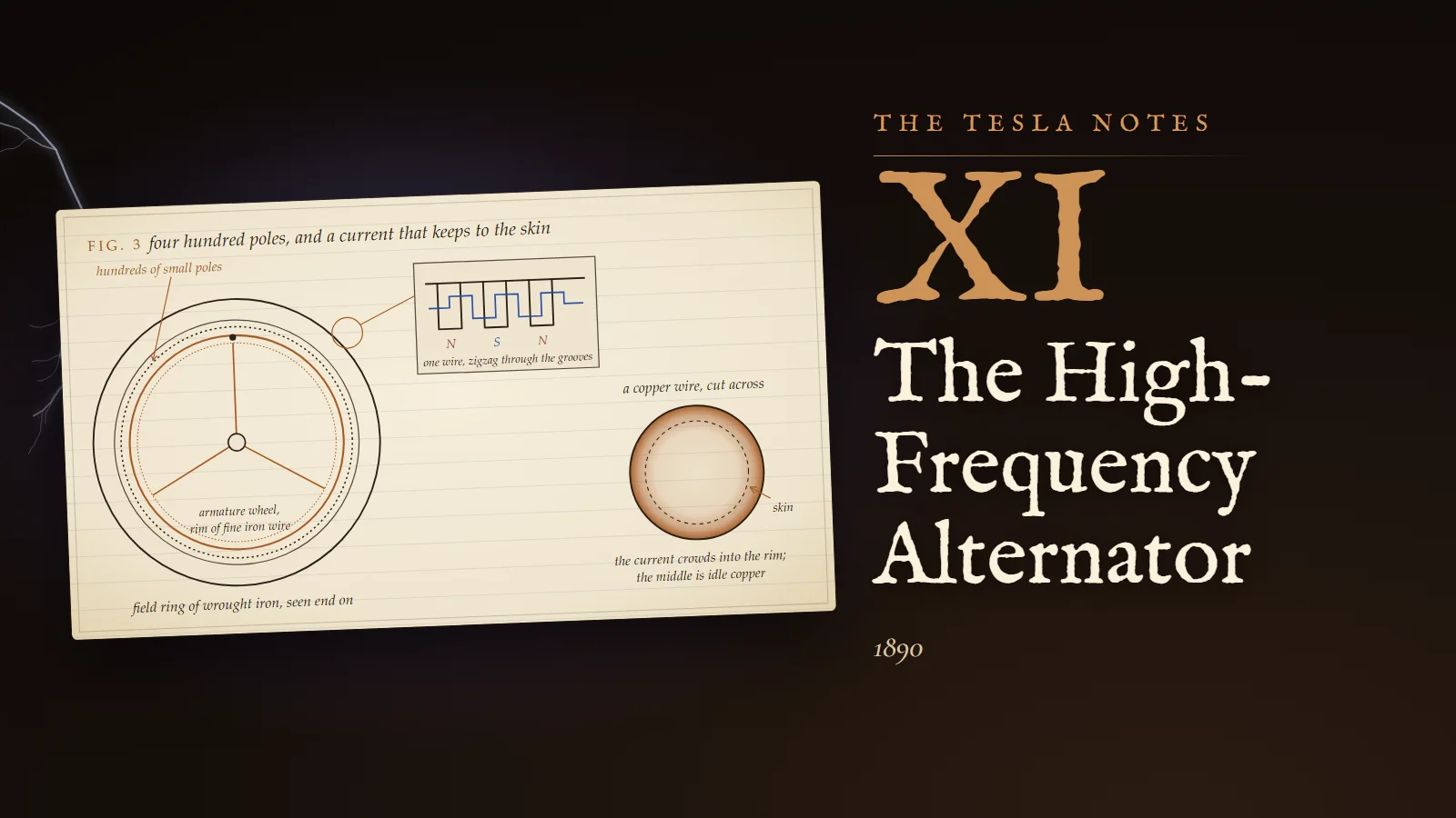
The field magnet is a ring of wrought iron with 384 pole projections on its inner face. The exciting coil is a single wire laid zigzag through the grooves between the projections, going down one groove and up the next, so that the current passes around each projection in the opposite sense to its neighbours. The poles are therefore alternately north and south, 192 of each, all excited by one circuit. The armature is a steel disc carrying a thin, carefully welded rim of wrought iron, and on the rim several layers of the fine annealed iron wire, shellacked. The armature conductors are wound zigzag around brass pins wrapped with silk thread, one bend of the wire for each pole, so that every bend is under a north pole when its neighbour is under a south pole and the electromotive forces in all the bends add together.
Draftsman's note
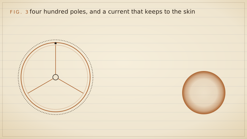
Fig. 3. The ring is drawn end on, much reduced, so the projections appear as a dotted inner circle; to draw all 384 at this scale would make a grey band. The armature wheel turns inside it in copper. The magnified window shows three projections and the single exciting wire, in blue, passing round them zigzag, with the poles lettered N, S, N. At the right, a copper wire cut across: dark at the rim, pale at the centre, for a reason I had not yet understood when the machine was built, and which the last entry of this book explains.
Calculation
The armature winding has a great many bends, each enclosing magnetic lines, and so it has a large self-induction. I measured it, by the bridge, at about two million centimetres. At 5,120 periods a second this self-induction opposes the current with a reactance of 2π × 5,120 × 2 × 10⁶ centimetres, which in ohms (10⁹ centimetres a second to the ohm) is 2π × 5,120 × 0.002 = 64 ohms. The armature resistance is under three ohms. So the machine, short-circuited, would deliver only a small part of the current its electromotive force could drive, and connected to a lamp of a few ohms it would deliver almost nothing. The self-induction is choking it.
The remedy is a condenser in series with the circuit. A condenser opposes the current in the opposite sense to a self-induction, with a reactance 1/(2πnC). When the two are equal they cancel exactly, and only the resistance is left.
- Set 2πnL = 1/(2πnC). Then C = 1/((2πn)² L).
- 2πn = 32,170. Squared: 1.035 × 10⁹. With L = 0.002 in practical measure: (2πn)² L = 2.07 × 10⁶. So C = 1/(2.07 × 10⁶) farad = 0.48 microfarad.
- That is a condenser of mica or paraffined paper about the size of a small book. With it in series, the current rises from E/64 to E/3, more than twenty times greater.
This is the same arithmetic as Kelvin's formula, read the other way. The armature's self-induction and the condenser form a circuit whose own frequency is 1/(2π√(LC)), and I have chosen the condenser so that this own frequency equals the frequency of the machine. The machine drives the circuit at its resonance, and the circuit takes as much current as the resistance allows.
Margin
The price of resonance is a sharp tune. If the belt slips and the speed falls by two per cent, the frequency falls by two per cent. The self-induction's reactance falls to 0.98 × 64 = 62.7 ohms; the condenser's rises to 64/0.98 = 65.3 ohms. They no longer cancel: 2.6 ohms of reactance remain against 3 ohms of resistance, and the current falls to 3/√(3² + 2.6²) = 0.76 of its value. At five per cent it falls to less than half. The machine must keep its speed to a per cent or two, and every lamp switched on or off changes the load on the engine. I shall need a governor better than any I have seen, or a way of tuning the condenser as the speed wanders.
Reflection
When the machine first ran at full speed it gave out a note, high and piercing, from the vibration of the projections themselves as the armature swept past them. At 10,000 alternations it is at the edge of what my ears can hear; the assistants, who are younger, hear it and complain. It is a strange sensation, to stand before a machine whose voice is the voice of its current. Nothing like it has existed before.
Grand Street, 1 October 1890. An arc that does not sing
I have filed today an application for a patent which is the first practical use I have found for the new machine. It concerns arc lamps, which hum on alternating currents and are a nuisance in every room they light.
Calculation
Why does an arc on an alternating current make a sound? The arc is a column of hot gas, and its heat at each instant is the square of the current multiplied by its resistance. If the current is I sin 2πnt, its square is I² sin² 2πnt, and since sin² θ = ½(1 − cos 2θ):
i² = ½ I² (1 − cos 4πnt)
The heating has a steady part, ½ I², and a part that varies at twice the frequency, 2n, which is to say at the rate of the alternations. The gas expands as it heats and contracts as it cools, at 2n times a second, and pushes the air in and out. The arc is a loudspeaker, and its note is the number of alternations.
- On the Westinghouse current, 16,000 alternations a minute, the arc hums at 267 vibrations a second, a little above middle C on the piano. Everyone in the room hears it.
- Raise the alternations to 10,000 a second, and the note is at the limit of hearing. Raise them further, and nobody hears anything. The heat still varies, but the air no longer answers in a way the ear can follow.
- There is a second gain. At low frequency the arc nearly goes out each time the current passes through zero, and must be relit; this flickering is a large part of the noise and a waste of light. At ten thousand alternations the gas has no time to cool between them, and the arc burns as steadily as on a continuous current.
The specification says what is needed in plain terms. The current must have "ten thousand or more alternations of current per second", which I describe as above "the limit of audition". For the machine I propose a field of "three hundred and seventy-five to four hundred poles" and an armature driven at "fifteen hundred or sixteen hundred revolutions per minute", giving "ten thousand or eleven thousand alternations". The armature core is to be "a mass of fine annealed iron wires", for the reasons I worked out in March. These are the numbers of the first entry of this book, and of the machine that now runs in the laboratory.
Reflection
An arc lamp is a small thing to file a patent on. But I want my name on the principle that frequency is a quantity to be chosen for the purpose, and that the purpose may want a great deal more of it than the dynamo builders have dreamed of. Today it is a silent arc. Next year it will be lamps without filaments, lit by the field of a coil.
Grand Street, 15 November 1890. A machine in which only iron turns
I have filed a second application today, for a generator that rearranges the first so that nothing turns except a wheel of iron.
In the first machine the armature conductors turn and the current must be taken from them through sliding contacts. Every sliding contact is a source of sparks and wear, and at these frequencies each brush also adds self-induction where I can least afford it. In the new design both the exciting coil and the armature conductors stand still. The field has two halves, each with serrated polar faces, the serrations of one face opposite those of the other. Between them, also fixed, are the conductors: a thin plate of copper sawn through in a zigzag, so that it forms one continuous conductor running back and forth across the faces. A wheel of iron with teeth to match the serrations turns in the gap. As each tooth comes opposite a pair of serrations it gives the magnetic lines an easy path across the gap; as it passes on, the path closes. The magnetism through each limb of the copper zigzag rises and falls, and the electromotive force alternates.
Calculation
- The specification asks that the field should vary "at points not farther distant from one another than the eighth of an inch". If the field changes from strong to weak in each eighth of an inch, one full period of the magnetism takes a quarter of an inch, 0.635 centimetre.
- With the rim of the iron wheel moving at 60 metres a second, 6,000 centimetres a second, the number of periods each second is 6,000/0.635 = 9,450, which is 18,900 alternations.
- The specification speaks of "say fifteen thousand per second or many more". At the speeds I can reach, and with teeth an eighth of an inch apart, fifteen to twenty thousand is what such a machine will give.
Reflection
I am uneasy about this design, and I write down why. In the first machine each conductor passes from a north pole to a south pole and back; the magnetism through it reverses, and with a careful shape of pole the electromotive force can be made very nearly a pure sine curve. In the second machine the magnetism through each conductor only rises and falls, between a strong value and a weaker one, without reversing. The varying part alternates, but how it alternates depends on the shape of the teeth, the leakage between them, and the saturation of the iron, and I cannot be sure it will be a sine. If it is not, it is a mixture of the fundamental frequency with its multiples, and when I tune a circuit to the fundamental the multiples will pass through it as a disturbance. For resonance I want a single pure tone. The first machine gives one; this one may give a chord.
Margin, added May 1891
At Columbia College I showed three machines and described them so that others could build them. Of the first I said, "The field magnet consists of a ring of wrought iron with 384 pole projections." The second, larger, has a field in two parts, and "Each part has 480 pole projections", with a wheel of hard bronze carrying the conductors between them. In the third, "only a block of wrought iron is revolved", and both armature conductors and exciting coil are kept stationary. I warned the investigator of two things above all: the local action in the conductors, which must be carefully avoided, and the clearance, which must be small. And of the armature wire in the first type: "The diameter of the armature wire in this type of machine should not be more than 1/6 of the thickness of the pole projections, else the local action will be considerable." Why that should be so is the subject of the next entry.
Grand Street, 20 December 1890. Where the current goes in a wire
The armature conductors of the first machine heat more than their resistance can account for. I measured the resistance of the armature with a steady current and calculated the heat the working current should produce in it; the armature warms nearly twice as fast. The iron, being fine wire, stays cool; the excess is in the copper. A heavy copper wire carrying a current of 5,000 periods behaves as if it were a thinner one. I have spent a month of evenings finding out why.
Calculation
Take the simplest case: a thick flat plate of copper, its face in the plane x = 0, extending to great depth in the direction x, with an alternating current flowing in it parallel to the face. Let i be the current density at depth x and time t, ρ the specific resistance and µ the permeability, all in absolute measure.
- The magnetic force H inside the metal, parallel to the face and at right angles to the current, changes with depth according to the current between: ∂H/∂x = 4πi, with the sense chosen suitably.
- The electromotive intensity driving the current is E = ρi. Faraday's law, applied to a small rectangle across the depth, gives ∂E/∂x = µ ∂H/∂t, so ρ ∂i/∂x = µ ∂H/∂t.
- Differentiate with respect to x and use step 1: ρ ∂²i/∂x² = µ ∂(∂H/∂x)/∂t = 4πµ ∂i/∂t. Therefore ∂²i/∂x² = (4πµ/ρ) ∂i/∂t. This is Fourier's equation for the conduction of heat. The current soaks into the metal from its surface as heat soaks into a cold bar from a hot face.
- At the surface the current alternates, I cos ωt, where ω = 2πn. Try a solution that alternates at every depth with a smaller amplitude and a later phase: i = I e^(−kx) cos(ωt − kx), with k to be found.
- Write u = ωt − kx. Then ∂i/∂x = Ik e^(−kx) (sin u − cos u), and differentiating again, ∂²i/∂x² = −2Ik² e^(−kx) sin u.
- And ∂i/∂t = −Iω e^(−kx) sin u.
- Put both into the equation of step 3: −2Ik² e^(−kx) sin u = (4πµ/ρ)(−Iω e^(−kx) sin u). Everything cancels except 2k² = 4πµω/ρ.
- So k = √(2πµω/ρ). The current falls to 1/e of its surface value, 37 per cent, at the depth δ = 1/k: δ = √(ρ/(2πµω)). Below a few times δ there is practically no current at all, and the copper there carries nothing.
Now the numbers, for copper, whose specific resistance is about 1,700 absolute units (1.7 microhms per centimetre cube) and µ = 1:
- At 60 periods, ω = 377: δ = √(1,700/(2π × 377)) = √(1,700/2,369) = √0.718 = 0.85 centimetre. A wire of a centimetre's diameter is used through its whole section.
- At 5,000 periods, ω = 31,416: δ = √(1,700/197,400) = √0.00861 = 0.093 centimetre, under a millimetre.
- At a million periods, the frequency of my Leyden jar circuits, ω = 6.28 × 10⁶: δ = √(1,700/3.95 × 10⁷) = 0.0066 centimetre, 66 thousandths of a millimetre, the thickness of a sheet of paper.
For a round wire whose radius a is several times δ, the current lives in a ring of thickness about δ at the surface, and the resistance to the alternating current is that of the ring: very nearly the resistance to steady current multiplied by a/(2δ) + ¼. My armature conductors are 6 millimetres thick, a = 0.3 cm, and at 5,120 periods δ = 0.092 cm, so the multiplier is 0.3/0.184 + 0.25 = 1.88. The resistance is nearly doubled, and the heat with it, which is what the thermometer told me.
Margin
Professor Lamb worked out the same effect for conducting spheres in 1883, and Mr. Heaviside gave the general theory of it in his articles of 1885 and after; I find that I have rediscovered, slowly and by my own road, what they had already printed. No matter. Knowing it by my own road, I know it to the bottom. And it changes how I must build. A thick round copper conductor is wasted at these frequencies. The conductors of a high-frequency machine should be of thin sheet copper, its thickness chosen to match the pole projections, or else made of many thin wires twisted together and insulated from one another, so that every part of the copper carries its share. For iron, whose permeability is several hundred and whose specific resistance is some six times that of copper, the skin is eight or ten times thinner: about a tenth of a millimetre at 5,000 periods, the thickness of the armature wire. The fine armature wire of the March entry was the right choice for a second reason.
Reflection
The machines work, and the frequencies I wanted are on my bench. But I see the end of this road. To reach a hundred thousand alternations I would need ten times the poles or ten times the speed, and the rim would fly apart or the clearance would vanish. The Leyden jar gives millions without moving a part. If I could join the steadiness of the machine to the speed of the jar, letting the machine charge a condenser and the condenser discharge through a coil, I could have both. That is the work of the coming months.
Problems I set myself
1. A machine is to give 20,000 alternations a second at 2,000 revolutions a minute. How many poles must it have, and what frequency is that in periods? If its armature is 75 centimetres across, how far apart are the poles and how fast does the rim move?
Answer. 2,000 revolutions a minute is 33⅓ a second, so the poles needed are 20,000/33.33 = 600. The frequency is 10,000 periods a second. The circumference is π × 75 = 235.6 centimetres, so each pole and gap occupies 235.6/600 = 0.39 centimetre, under a sixth of an inch. The rim moves at 235.6 × 33.33 = 7,850 centimetres a second, 78.5 metres a second.
2. Find the skin depth in copper at 10,000 periods a second, and the ratio of the resistance to alternating current to the resistance to steady current for a copper wire 4 millimetres in diameter.
Answer. ω = 2π × 10,000 = 62,830. δ = √(1,700/(2π × 62,830)) = √(1,700/394,800) = √0.00431 = 0.066 centimetre, 0.66 millimetre. The radius is 0.2 centimetre, three times δ. The multiplier is a/(2δ) + ¼ = 0.2/0.132 + 0.25 = 1.77. The full theory of the round wire, with Bessel's functions, gives 1.78, so the simple rule is good to one per cent even here.
3. An armature has a self-induction of two million centimetres and a resistance of 2 ohms, and runs at 5,000 periods. Find the series condenser that cancels the self-induction. If the speed then falls by 2 per cent, by what fraction does the current fall?
Answer. ω = 31,420, and L = 0.002 in practical measure, so ωL = 62.8 ohms. C = 1/(ω²L) = 1/(9.87 × 10⁸ × 0.002) = 0.51 microfarad. At 2 per cent less speed the coil's reactance is 0.98 × 62.8 = 61.6 ohms and the condenser's 62.8/0.98 = 64.1 ohms, leaving 2.5 ohms of reactance. The current falls from E/2 to E/√(2² + 2.5²) = E/3.2, to 0.62 of its value. Lower resistance makes the tune sharper and the loss from a wandering speed greater.
To the student who reads this later
You will recognise my "absolute units" as the centimetre-gram-second electromagnetic system: a self-induction of two million centimetres is your 2 millihenries, a specific resistance of 1,700 absolute units your 1.7 × 10⁻⁸ ohm-metre. In your units the skin depth is δ = √(2ρ/(ωµ)), with µ = µ₀µr and µ₀ = 4π × 10⁻⁷, which gives the same 0.93 millimetre for copper at 5 kilohertz and 9.3 millimetres at 50 hertz. Your exact formula for a round wire uses the Bessel functions of complex argument, the ber and bei functions; the readout of Plate XI uses them. My eddy-current formula P = π²f²B²d²/(6ρ) is your classical lamination loss, exact when the sheet is thinner than its own skin depth and an overestimate when it is not.
On the history. I did build high-frequency alternators of 384 and 480 poles in 1890 and showed them in 1891, and they were the first machines to give a steady current at frequencies near and above the limit of hearing. The second patent of November 1890, US 447,921, is in fact an inductor alternator, with stationary windings and a revolving toothed iron wheel; so is the third machine of my 1891 lecture. When I wrote in 1919 that I had rejected the inductor type, I meant that I had not pursued it as the road to higher frequencies, because I feared it would not give a pure sine wave; I had built it, and patented it, and then turned away from it. Others did not. Ernst Alexanderson at General Electric, from 1904, perfected the inductor alternator into the great radio machines: a solid steel disc with hundreds of slots around its rim, turning at some two thousand revolutions a minute, giving 200 kilowatts at tens of kilohertz for transatlantic telegraphy. One still runs at Grimeton in Sweden and transmits on special days at 17.2 kilohertz. The labour I could have saved myself is the labour he did.
The skin effect is everywhere in your work. Your radio-frequency coils are wound with litz wire, many fine strands insulated and woven so that each takes its turn at the surface, which is my "twisted thin wires". Your transformer cores at high frequency are ferrite, an insulating magnetic ceramic, in which eddy currents have no metal path at all. Your induction cooktops work at 20 to 100 kilohertz so that the heat appears in a thin skin of the pan, and your induction furnaces choose their frequency so that the skin depth suits the size of the charge. Your power lines carry their current in aluminium strands around a steel core, because at 50 or 60 hertz the outer centimetre carries most of the current anyway. What to try: wind a coil of a few turns of thick wire, drive it from an audio amplifier at 20 kilohertz, and drop in a short length of iron wire and then a length of copper of the same thickness; feel which warms, and how fast.
If you want to argue with me about the inductor type, or about whether I should have built bigger machines and fewer coils, come and ask me.
Sources and liberties
The Tesla Notes are a modern reconstruction written in Nikola Tesla's voice by Eternal Gardens. Dates, patents, lectures, apparatus and quotations come from the sources below; the private reflections, the order of the working and the sketches are ours.
- Nikola Tesla, "My Inventions", Part IV, Electrical Experimenter, May 1919 (the return to Grand Street at the close of 1889, the design of high-frequency machines, the rejection of the inductor type, and the inconstancy of speed that made the tune lost): Wikisource
- Nikola Tesla, US Patent 447,920, "Method of Operating Arc-Lamps", filed 1 October 1890, granted 10 March 1891 (the quoted alternations, poles and speeds, and the armature of fine iron wire): Google Patents
- Nikola Tesla, US Patent 447,921, "Alternating-Electric-Current Generator", filed 15 November 1890, granted 10 March 1891 (serrated polar faces, the zigzag copper plate, the revolving iron, and the quoted spacing and frequency): Google Patents
- Nikola Tesla, "Experiments with Alternate Currents of Very High Frequency and Their Application to Methods of Artificial Illumination", AIEE, Columbia College, 20 May 1891 (the three machines, the 384 and 480 pole projections, the iron wire passed through shellac, the brass pins and silk thread, the one-sixth rule, sheet copper or twisted thin wires, and the iron core that grows excessively hot): text at tfcbooks.com
- Skin effect: H. Lamb, "On Electrical Motions in a Spherical Conductor", Philosophical Transactions, 1883; O. Heaviside, articles in The Electrician from 1885; general account: Wikipedia
- Eddy-current loss in laminations: Wikipedia
- The Alexanderson alternator and the Grimeton station: Wikipedia; UNESCO World Heritage List, Varberg Radio Station
- W. B. Carlson, Tesla: Inventor of the Electrical Age (Princeton University Press, 2013), for the Grand Street laboratory and the alternator work of 1890.
The patents and the lecture give the numbers of poles, speeds and frequencies, and the construction of the machines; they do not give the armature dimensions, its self-induction, or the condenser used with it. The wheel diameter of thirty inches, the self-induction of two million centimetres, the measured heating of the armature copper, and the dates of the March, July and December entries are the notebook's illustrative reconstruction. Tesla's eddy-current and skin-depth calculations are written in the notation of his time; there is no record that he derived the skin effect himself, and the entry presents it as his own working of a result Lamb and Heaviside had published.