





Grand Street, January 1891. I have two sources of rapid alternation on my bench and neither will do what I want. The alternators of last year give ten or twenty thousand alternations a second, steadily, but they will go no faster without flying apart. The Leyden jar gives a million and more, but at the potential to which it was charged and no higher, and the potential I need for my lamps and tubes is a hundred thousand volts. The ordinary induction coil should raise the potential, and at these frequencies it fails completely. This book records the three months in which I found out why it fails and what to put in its place: a transformer with no iron, a primary of a few turns fed by a condenser through a spark, and a secondary tuned to it so that the two circuits swing as one. Of everything I have made, I believe this will be used longest.
When in 1900 I obtained powerful discharges of 100 feet and flashed a current around the globe, I was reminded of the first tiny spark I observed in my Grand Street laboratory and was thrilled by sensations akin to those I felt when I discovered the rotating magnetic field.
Nikola Tesla, "My Inventions", Part IV, Electrical Experimenter, May 1919
Grand Street, 12 January 1891. Why the induction coil fails
I connected the largest Ruhmkorff coil in the laboratory to the alternator, through its primary, at 10,000 alternations a second. I expected sparks of many inches. I got a fizzing at the terminals hardly an eighth of an inch long, while the iron core grew so hot that I had to stop after a minute. With the alternator slowed, the spark lengthened. The coil, made for the slow make and break of a hammer interrupter, wants a lower frequency. I have spent a week finding out exactly why.
Calculation
The secondary of a large induction coil is many miles of fine wire, perhaps twenty thousand turns, wound in layers on a core of iron wire. It has an enormous self-induction. It also has capacity: every turn is a small condenser plate facing its neighbours and the layers beneath, so that the capacity is distributed all along the coil. A coil with self-induction and capacity has a period of its own, exactly as the Leyden jar and its loop have, and Kelvin's formula gives it.
- I estimate the self-induction of this secondary, with its core in place, at about 3 × 10¹⁰ centimetres, and its own capacity, from the length of wire and the thickness of the insulation, at about 45 centimetres, about that of a sphere three feet across.
- T = 2π√(LC)/v = 2π√(3 × 10¹⁰ × 45)/(3 × 10¹⁰) = 2π × 1.16 × 10⁶/(3 × 10¹⁰) = 2.43 × 10⁻⁴ second.
- So the coil has its own frequency of about 4,100 periods a second. Below this, its secondary behaves as a self-induction, and the potential rises with the ratio of turns, as it does on a hammer interrupter. Above it, the secondary behaves as a condenser: the current it draws to charge its own capacity exceeds the current the primary can induce in it, and the potential at the terminals falls with every increase of frequency.
- My alternator, at 5,000 periods, is above that frequency. A coil big enough to give long sparks from slow currents is too big for fast ones. Capacity added at the terminals lowers the coil's own frequency further and makes matters worse.
And the iron. In the last book I found that the heat in iron grows as the square of the frequency. A core of iron wire that is warm at fifty interruptions a second is red at ten thousand. At a million periods the iron would be worse than useless; the eddy currents in it would screen the secondary from the primary entirely.
Reflection
Every part of the induction coil was designed for a world of slow currents: the iron, the thousands of turns, the thin primary of many layers. Each part fights me at high frequency. The lesson is that a coil for rapid alternations must be small in the right way: few turns, so that its own frequency is high; no iron, so that nothing heats; and wide spacing between primary and secondary, so that the enormous potential cannot break through. But a coil with few turns and no iron has a small self-induction and a weak coupling between its windings, and by the ordinary rule it should raise the potential very little. The ordinary rule, I begin to suspect, does not apply.
Grand Street, 9 February 1891. A happy inspiration
The idea came while I was watching the spark of the Leyden jar circuit, the one that gives a million periods from four jars and a loop of rod. The loop is a primary already. Its current is enormous, hundreds of amperes, and it swings a million times a second. Put a coil of a few hundred turns near it, with no iron, and the rate of change of the magnetism through that coil is so great that a large electromotive force must be induced in every turn, though the primary has only one turn and the coupling is loose. The rapidity of the change does what the multitude of turns and the iron did in the old coil.
Then the further thought, which is the important one. The secondary coil has its own period, from its self-induction and its distributed capacity. The primary circuit, condenser and loop, has its own period too. If I make the two periods equal, the secondary will answer the primary as one tuning fork answers another of the same pitch, and each swing of the primary will add to the swing of the secondary until a large part of the energy of the condenser has passed across.
Calculation
The design I shall build first. Primary: three turns of heavy copper strip around a tube of hard rubber, with a self-induction of about 8,000 centimetres. Condenser: Leyden jars in multiple arc, of 9,000 centimetres together, about one hundredth of a microfarad. Secondary: 500 turns of fine wire wound in a single layer on a tube 10 centimetres in diameter and 40 centimetres long, standing inside the primary.
- The own period of the primary: T₁ = 2π√(L₁C₁)/v = 2π√(8,000 × 9,000)/(3 × 10¹⁰) = 2π × 8,485/(3 × 10¹⁰) = 1.78 × 10⁻⁶ second. Its frequency is 563,000 periods a second.
- The self-induction of the secondary, a long solenoid: L₂ = 4π²a²N²/l, with a = 5, N = 500 and l = 40, gives 39.48 × 25 × 250,000/40 = 6.17 × 10⁶ centimetres. Less about a tenth for the ends of the coil, where the lines spread out: L₂ ≈ 5.5 × 10⁶ centimetres.
- For the two circuits to be in tune their periods must be equal, so L₂C₂ = L₁C₁. The capacity of the secondary, its own distributed capacity together with that of its terminals, must then be C₂ = L₁C₁/L₂ = 8,000 × 9,000/(5.5 × 10⁶) = 13 centimetres. That is the capacity of a sphere a little more than ten inches across. Small terminals and the coil's own capacity will make it, and I can adjust the tune by changing the terminals.
- What potential can the secondary reach? If all the energy of the charged condenser passes into the secondary, ½C₁V₁² = ½C₂V₂², and so V₂/V₁ = √(C₁/C₂). Since L₁C₁ = L₂C₂, C₁/C₂ = L₂/L₁, and therefore V₂/V₁ = √(L₂/L₁).
- Here L₂/L₁ = 5.5 × 10⁶/8,000 = 690, and √690 = 26. A condenser charged to 10,000 volts could, if nothing were lost, raise the secondary to 260,000 volts.
This is the result that matters. The ratio of potentials is set by the square root of the ratio of self-inductions, and the number of turns enters only through that. The ratio of turns, which governs the ordinary transformer, is beside the point: here it is 500 to 3, but it is the tune and the energy that decide.
Draftsman's note
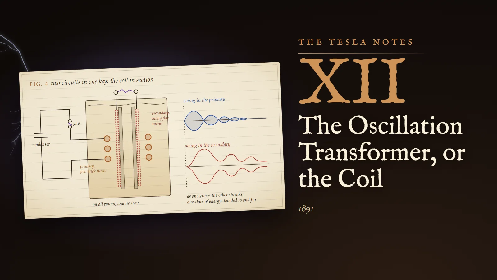
Fig. 4. Cut through the axis, so that each turn of the primary appears twice, as a large copper circle on either side, and the secondary as two columns of small red dots on the walls of its tube. Here the primary is drawn outside the secondary, which is how I shall wind the first; I have also tried it inside the tube, close against the secondary's lowest turns, and will choose by trial. The condenser and gap are at the left; the gap is drawn with its violet spark. The secondary's two ends rise out of the oil to small balls, between which the long spark passes. At the right, the two swings drawn one above the other: the primary's dying away as the secondary's grows, then reviving as the secondary's falls. A dotted line moves across them as time.
Margin
The charging. The condenser must be charged between discharges, and the alternator gives only some hundreds of volts. A small step-up transformer between the alternator and the condenser, or an ordinary induction coil, raises its potential to the ten or twenty thousand volts at which the gap breaks down. The alternator then charges the condenser, the condenser discharges through the gap into the primary, the primary rings for some microseconds and hands its energy to the secondary, the gap goes cold, and the alternator charges the condenser again. Thousands of these little trains each second. The slow machine feeds the fast circuit, and each does what it is good at.
Grand Street, 2 March 1891. Two pendulums on one string
The coil works. With the condenser charged from the alternator through a small step-up transformer, the secondary gives sparks of an inch and a half between its terminals, from a coil of five hundred turns which on the old rule should give a tenth of an inch. But it does not behave as I expected. The sparks are longest when the secondary is set some way above the primary. Bring the coils closer together and the sparks shorten. I have spent two weeks of evenings understanding why, and the answer is the most beautiful calculation I have made since the rotating field.
Calculation
Let the primary have self-induction L₁, condenser C₁ and charge q₁; the secondary L₂, capacity C₂ and charge q₂; M the coefficient of mutual induction between them. Let losses be neglected for the present. The currents are i₁ = dq₁/dt and i₂ = dq₂/dt.
- In each circuit the electromotive forces around it sum to zero. For the primary: L₁ d²q₁/dt² + M d²q₂/dt² + q₁/C₁ = 0. For the secondary: L₂ d²q₂/dt² + M d²q₁/dt² + q₂/C₂ = 0.
- Let both circuits be tuned to the same own frequency n₀, and write ω₀ = 2πn₀, so that 1/(L₁C₁) = 1/(L₂C₂) = ω₀². Divide the first equation by L₁ and the second by L₂: d²q₁/dt² + (M/L₁) d²q₂/dt² + ω₀² q₁ = 0, and d²q₂/dt² + (M/L₂) d²q₁/dt² + ω₀² q₂ = 0.
- Seek a motion in which both charges swing together at one frequency ω: q₁ = A cos ωt, q₂ = B cos ωt. Each second derivative is −ω² times the quantity. Substituting: (ω₀² − ω²)A = (M/L₁) ω² B, and (ω₀² − ω²)B = (M/L₂) ω² A.
- Multiply these two equations together and divide by AB: (ω₀² − ω²)² = (M²/(L₁L₂)) ω⁴.
- Call k = M/√(L₁L₂) the coefficient of coupling: the fraction of the greatest mutual induction the coils could possibly have. It is 1 if every line through one passes through the other, and in my coil, with no iron and an inch of oil between the windings, it is perhaps 0.1 to 0.3. Then ω₀² − ω² = ±kω², and so ω² = ω₀²/(1 ± k).
- There are two frequencies: ω₋ = ω₀/√(1 + k), a little below the tune, and ω₊ = ω₀/√(1 − k), a little above. For k = 0.15: 0.933 ω₀ and 1.085 ω₀. In the lower one the two circuits swing together; in the upper, against each other. From step 3, B/A = ±√(L₁/L₂) in the two cases.
- Now start with the condenser charged, q₁ = Q, and the secondary empty, q₂ = 0. This is an equal mixture of the two motions, the one with the secondary in step and the one with it reversed, so that their secondary parts cancel at the start: q₁ = ½Q(cos ω₋t + cos ω₊t), q₂ = ½Q√(L₁/L₂)(cos ω₋t − cos ω₊t), the sign of q₂ depending on the sense of winding.
- By the rule for adding cosines: q₁ = Q cos(½(ω₊ − ω₋)t) cos(½(ω₊ + ω₋)t), and q₂ = Q√(L₁/L₂) sin(½(ω₊ − ω₋)t) sin(½(ω₊ + ω₋)t). Each is a rapid swing at nearly ω₀, whose amplitude rises and falls slowly. When the primary's amplitude is greatest the secondary's is zero, and the reverse. They beat.
- The secondary is fullest when ½(ω₊ − ω₋)t = π/2, that is t = π/(ω₊ − ω₋). In periods of the tune, 2π/ω₀, this is ω₀/(2(ω₊ − ω₋)). For small k, ω₊ − ω₋ ≈ kω₀, and the energy has all passed across after 1/(2k) periods. For k = 0.15: 1/(2 × 0.152) = 3.3 periods. For k = 0.3, 1.6 periods.
- At that moment the secondary's charge is Q√(L₁/L₂), and its potential Q√(L₁/L₂)/C₂. Divide by the primary's initial potential Q/C₁: the ratio is (C₁/C₂)√(L₁/L₂) = (L₂/L₁)√(L₁/L₂) = √(L₂/L₁). The same 26 as in February, now reached by a different road.
So the energy flows from the primary into the secondary in 1/(2k) periods, and then, if nothing stops it, flows back again, and across again, as long as the oscillation lasts. Two pendulums of equal length hung from one slack string do exactly this: set one swinging and it slowly stops while the other starts, and then the first takes the motion back. The coupling is the string.
Experiment No. 1
The secondary mounted on a slide, so that it can be raised out of the primary by measured steps. Spark length between the terminals measured at each step, with the condenser charged from the alternator at the same potential throughout.
Results. With the secondary close inside the primary, the coupling tightest, the spark is short, and streamers creep along the tube toward the primary; at the closest setting the insulation failed between the two windings and I had to rewind the lowest layers. Raised two inches, the spark is longest, an inch and three quarters. Raised further, the spark shortens again, and at six inches it is a fraction of an inch. With the terminals changed for larger ones, to add capacity, the best position shifts and the best spark is shorter.
Reflection
Three things are at work, and the calculation shows all three. Tight coupling sends the energy across in a period or two, which is good, for the spark is consuming it all the while; but tight coupling also means the primary's great potential is brought close to the secondary's, and the streamers between them waste the energy and destroy the insulation. Loose coupling keeps the two apart but takes so many periods to transfer that the spark has eaten most of the energy first. In between there is a best setting, and I have found it by trial. The larger terminals detuned the secondary, adding to its capacity, and a detuned secondary takes less of the energy at any coupling. The tune is everything.
Grand Street, 6 April 1891. The spark: thief and switch
The spark gap is the heart of the arrangement and its weakest part. It is the switch, which closes when the condenser is full and lets the energy into the primary; and it is a thief, a resistance in the primary circuit, consuming energy as heat and light at every swing.
Calculation
- The resistance of a spark of a few millimetres, carrying hundreds of amperes, I estimate from the dying of the primary oscillation with the secondary removed: the swing falls to 1/e of its value, a little over a third, in about seven periods. In the last book I found that the swing falls by e^(−πR/(ωL)) each period. Seven periods to fall to 1/e is ωL/(πR) = 7, so R = ωL/(7π).
- For the primary of this coil, ωL₁ in ohms is 2π × 563,000 × 8,000/10⁹ = 28.3 ohms. So R = 28.3/22 = 1.3 ohms, nearly all of it in the spark, and the primary's quality, ωL/R, is about 22.
- The secondary, by the same method, decays far more slowly: its swing falls to 1/e in some forty-five periods, a quality near 140. Its fine wire has more resistance than the primary's strip, but its self-induction is 690 times larger.
- Now compare times. With k = 0.15 the energy takes 3.3 periods to cross. In 3.3 periods the primary alone, with quality 22, would lose a fraction 1 − e^(−2π × 3.3/22) = 1 − e^(−0.94) = 0.61 of its energy. But during the transfer the primary current is falling, and the loss with it; working through the beat, the spark takes something like two-fifths of the energy before the secondary is fullest, and the secondary receives perhaps three-fifths. Then the potential reaches √0.6 × 26 = 20 times the condenser's, against an ideal 26.
- With k = 0.3 the transfer takes 1.6 periods, the spark takes a fifth, and four-fifths arrive. This is why tight coupling is so valuable, up to the point where the insulation fails.
Margin
A thought I cannot yet realise. At the moment the secondary is fullest, the primary current is zero. If the spark went out then, and stayed out, the energy would be trapped in the secondary, which loses it slowly, and it could not come back to be wasted in the gap. The spark does not go out: the gap is hot and ionised and conducts again as the primary current revives. A gap that cooled instantly, by a blast of air, or a magnet blowing the arc aside, or many short gaps in series between massive cooling plates, would turn the beat into a single delivery. Plate XII, with the spark made to go out at the first null, shows what I would gain.
Experiment No. 2
The coil immersed in a vessel of paraffin oil, after the windings had been dried and the air boiled out of them. Results: the sparks lengthen by half, and no streamers creep along the tube even at the tightest coupling. The secondary can be brought close to the primary without breakdown, so that k can be raised. The oil excludes the air entirely, and it is the air in the pores and corners of the insulation, breaking down into streamers under the enormous strain, that destroyed the windings before. The vessel is a nuisance in the laboratory, but every high-potential coil I make from now will stand in oil.
Grand Street, 25 April 1891. Patent application, system of electric lighting
I have signed and filed today the application for the patent on the whole arrangement, framed as a system of lighting, because lighting is what I shall use it for first and what the examiners will understand. The specification states the principle in one sentence: "an electrical current of an excessively small period and very high potential may be utilized economically and practicably to great advantage for the production of light." As to frequency, I wrote that good results follow from "a frequency as low as fifteen thousand to twenty thousand per second and a potential of about twenty thousand volts", which are the figures of my alternator and of the condenser's charge; the transformer will multiply both.
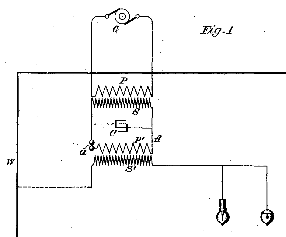
The drawing is the whole chain of this book in one row: the generator G, the transformer P S that raises its potential to charge the condenser C, the air-gap a across which the condenser discharges into the circuit A, the primary P′ of a few turns, and the secondary S′ of long fine wire, which leads to the lamps. Of the discharge itself I wrote: "Such a discharge is known to be, under proper conditions, intermittent or oscillating in character." Kelvin's equation is in that sentence, and so is the turning mirror of the winter before last.
The third claim is the one I care for most. It claims the method of "charging a condenser by a given current, maintaining an intermittent or oscillatory discharge of said condenser through or into a primary circuit, and producing thereby in a secondary working-circuit in inductive relation to the primary very high potentials". That is the oscillation transformer, described as a method, so that whoever builds one by any construction is within it.
Reflection
For the lamps I have written that the light may come from "molecular bombardment, condenser action, and electric or etheric disturbances", which is a careful way of saying that I do not yet know which. The patent claims what I have done and leaves the explanation open. I am content with that. The thing works before it is understood, as the rotating field did.
Grand Street, 4 May 1891. Five inches
The Institute has asked me to show my high-frequency experiments at Columbia College on the 20th, and I am building a coil for it. Today the new coil, larger than the first, wound with the experience of the last two months and standing in oil, gave a spark of five inches between its terminals: a thick, crackling, violet-white stream, branching at the ends, with a sound like a whip, thousands of times a second.
Calculation
- How high is the potential? For short sparks between balls in air, breakdown takes about 30,000 volts for each centimetre. For long sparks between points the stress needed falls, because the air ahead of the spark is already broken down by its streamers, and from my own spark-gauge measurements five inches, 12.7 centimetres, between points takes something like 100,000 volts at these frequencies. The uncertainty is large, a quarter either way.
- If the condenser is charged to 15,000 volts, the secondary is at some seven times that. With this coil's ratio of self-inductions, about 400, the ideal multiplication would be 20; the losses in the spark and coupling looser than I could wish leave me a third of the ideal. Better than the old coil, which gave an eighth of an inch at these frequencies, by a factor of forty in spark length.
- Energy per spark. The condenser of 0.02 microfarad at 15,000 volts holds ½ × 2 × 10⁻⁸ × (15,000)² = 2.25 joules. At 1,000 discharges a second, from the alternator's charging, this is 2,250 watts flowing through the gap. Most of what is lost is lost there: the gap glows white and must be blown upon with air to keep it from arcing over.
Reflection
I sat in the dark laboratory after the assistants had gone and watched it for an hour. A spark five inches long, from a coil you could carry under your arm, with no iron in it, fed by a machine that turns at ordinary speed. A year ago this was impossible. The coil in the oil makes a low hum and the spark makes a sound like tearing cloth. I keep thinking of the first spark, the tiny one in the turning mirror, a quarter of an inch long, whose images told me the current swings. Everything since has been that spark, made larger by understanding it. I do not know how far this goes. I suspect much farther than five inches.
Problems I set myself
1. A primary has a self-induction of 10,000 centimetres and a condenser of 0.02 microfarad (18,000 centimetres). The secondary's self-induction is 8 × 10⁶ centimetres. Find the own frequency of the primary, and the capacity the secondary must have to be in tune.
Answer. T₁ = 2π√(10,000 × 18,000)/(3 × 10¹⁰) = 2π × 13,416/(3 × 10¹⁰) = 2.81 × 10⁻⁶ second, so the frequency is 356,000 periods a second. C₂ = L₁C₁/L₂ = 10,000 × 18,000/(8 × 10⁶) = 22.5 centimetres, about 25 millionths of a microfarad: the capacity of a sphere 45 centimetres across, or of a modest terminal together with the coil's own distributed capacity.
2. In the same coil the condenser is charged to 15,000 volts. What is the energy in the condenser, and what potential would the secondary reach if all of it passed across? What if only three-fifths does?
Answer. Energy ½C₁V₁² = ½ × 2 × 10⁻⁸ × (1.5 × 10⁴)² = 2.25 joules. The multiplication is √(L₂/L₁) = √800 = 28.3, so the ideal secondary potential is 28.3 × 15,000 = 424,000 volts. Check by energy: the secondary's capacity is 22.5 centimetres, 2.5 × 10⁻¹¹ farad, and ½ × 2.5 × 10⁻¹¹ × (4.24 × 10⁵)² = 2.25 joules. With three-fifths of the energy the potential is √0.6 = 0.775 of that, 329,000 volts.
3. The coupling is 0.2 and the tune 563,000 periods a second. After how many periods, and how many millionths of a second, is the secondary fullest? If the spark could be made to go out at that instant, how long would the primary have been conducting?
Answer. ω₋ = ω₀/√1.2 = 0.913 ω₀ and ω₊ = ω₀/√0.8 = 1.118 ω₀, so ω₊ − ω₋ = 0.205 ω₀, and the time is 1/(2 × 0.205) = 2.44 periods (the rule 1/(2k) gives 2.5). One period of the tune is 1/563,000 = 1.78 millionths of a second, so the secondary is fullest after 4.3 millionths of a second, and the spark need conduct no longer than that.
To the student who reads this later
You call it the Tesla coil, and I am glad of the name. In your notation the coupled circuits are L₁q̈₁ + Mq̈₂ + q₁/C₁ = 0 and L₂q̈₂ + Mq̈₁ + q₂/C₂ = 0; the normal modes ω = ω₀/√(1 ± k), the beat, and the transfer time are exactly as I derived them, and coupled-mode theory generalises them to any pair of resonators, optical, acoustic or mechanical. My self-inductions in centimetres convert at 10⁹ centimetres to the henry: the primary of 8,000 centimetres is your 8 microhenries, the secondary of 5.5 million is 5.5 millihenries, and my capacities convert at about 0.9 centimetre to the picofarad. The voltage gain √(L₂/L₁) for a tuned, lossless coil is standard in every textbook on Tesla coils.
The history, honestly told. The patent on this arrangement, US 454,622, was filed on 25 April 1891 and granted on 23 June 1891. Whether I tuned primary and secondary deliberately from the first, as these entries have me do, is less certain than the design itself; I wrote of the importance of tuning at length in my lecture of 1893 and in later patents, and in 1919 I said that "by proper proportioning of the resonant circuits an efficiency of 85 per cent is attainable." I also acknowledged openly that the spark gap was a defect of the method, a loss I never fully removed. The quenched gap I imagined in April was made practical by Max Wien in 1906, with many short gaps between cooled plates, and it made spark wireless telegraphy far more efficient. In 1943 the Supreme Court of the United States, in Marconi Wireless Telegraph Co. of America v. United States, 320 U.S. 1, held the principal claims of Marconi's four-circuit tuning patent invalid, citing the earlier work of Oliver Lodge, John Stone Stone and myself on tuned circuits. I did not live to read the decision; I died in January of that year.
Where you use it. Every radio receiver of the spark era, and many since, had tuned coupled circuits exactly like these, with the coupling adjusted for selectivity. The intermediate-frequency transformers of your superheterodyne radios are pairs of tuned coils whose coupling is set just at the point where the two modes begin to separate. In 2007 a group at the Massachusetts Institute of Technology lit a 60-watt lamp two metres from its source using two coupled resonant coils, which they called strongly coupled magnetic resonance; your wireless chargers and the charging pads of electric cars are its descendants. And the coil itself, as a machine for long sparks, is built by students, hobbyists and museums the world over, with a quarter-wavelength secondary and a primary that is often just a flat spiral of copper tube.
A warning, from someone who was careless with these things for fifty years and lucky. The primary condenser of even a small coil stores energy enough to kill, at a potential that jumps any gap you leave it. The secondary's sparks look harmless because the high frequency keeps them on the skin, but they burn, they set fire to anything they touch, and they make ozone and nitrous gases in a closed room. If you build one, build it with someone who has built one before, discharge the condenser with an insulated rod every time before you touch anything, and keep a wooden stick between yourself and the terminal.
If you want to know what the first five-inch spark sounded like, or why I never stopped improving this coil, come and ask me.
Sources and liberties
The Tesla Notes are a modern reconstruction written in Nikola Tesla's voice by Eternal Gardens. Dates, patents, lectures, apparatus and quotations come from the sources below; the private reflections, the order of the working and the sketches are ours.
- Nikola Tesla, US Patent 454,622, "System of Electric Lighting", filed 25 April 1891, granted 23 June 1891 (the quoted principle, frequency and potential, the oscillating discharge, the lamp hypotheses, the third claim, and Fig. 1): Google Patents
- Patent 454,622, Fig. 1, public domain: Wikimedia Commons
- Nikola Tesla, "My Inventions", Part IV, Electrical Experimenter, May 1919 (the epigraph, the five-inch coil of 1891, the loss in the spark gap, and the efficiency of 85 per cent): Wikisource
- Nikola Tesla, "The True Wireless", Electrical Experimenter, May 1919 (the powerful induction coil, the "happy inspiration" that led to the oscillation transformer): Wikisource
- Nikola Tesla, "Experiments with Alternate Currents of Very High Frequency and Their Application to Methods of Artificial Illumination", AIEE, 20 May 1891 (the large coil that gives under an eighth of an inch at high frequency, its distributed capacity, the condenser and discharging circuit feeding a small auxiliary coil of few turns, oil insulation and the exclusion of air): text at tfcbooks.com
- Nikola Tesla, "Experiments with Alternate Currents of High Potential and High Frequency", IEE, London, 3 February 1892 (the later coil in oil, and the remark that the ratio of turns does not convey the ratio of electromotive forces at high frequency): text at tfcbooks.com
- Marconi Wireless Telegraph Co. of America v. United States, 320 U.S. 1 (1943): Justia
- Quenched spark gap (Max Wien, 1906): Wikipedia
- A. Kurs and others, "Wireless Power Transfer via Strongly Coupled Magnetic Resonances", Science 317 (2007), 83 to 86: Science
- The Tesla coil, its theory and history: Wikipedia
The patent, the lectures and "My Inventions" establish the arrangement, its date, the five-inch spark of 1891 and the loss in the gap. The dimensions of the first coil, its self-inductions and capacities, the measured qualities of the circuits, the coupling experiments and the oil experiment as dated here are the notebook's reconstruction, made to agree with the physics and with the apparatus Tesla described in 1891 and 1892. Whether Tesla tuned primary and secondary deliberately in the spring of 1891 is debated; his explicit treatment of tuning comes in the lecture of 1893 and later patents, and the entries give him the arithmetic early.